4-3 Manually Setting Data Links
4-3-11 Transferring the Data Link Table
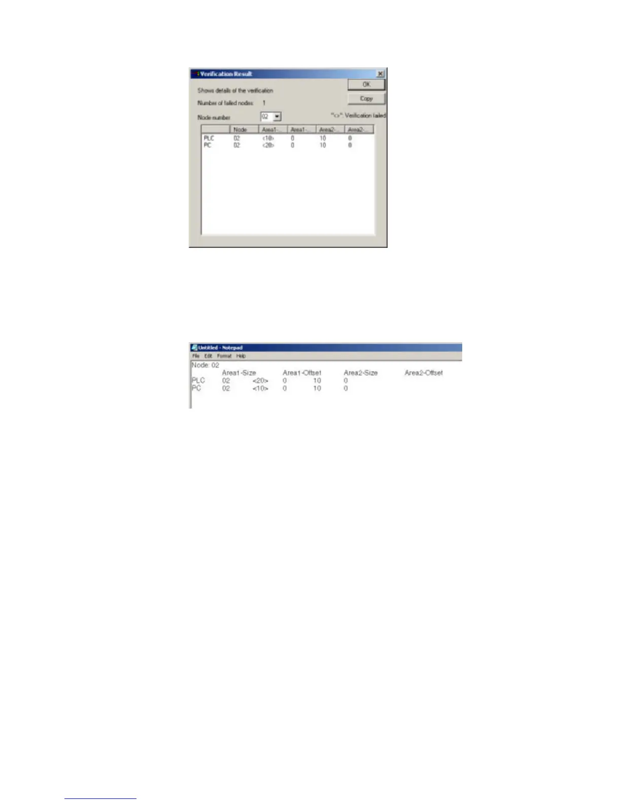
Select the node address to display the data link area data for both the PLC and in
the computer for the specified node address: Area 1 Size, Area 1 Offset, Area 2
Size, and Area 2 Offset. The size of this dialog box can be changed.
The data for the PLC is display on top and that for the computer (i.e., the data
being edited on the CX-Integrator) is displayed on bottom. Inconsistencies are
displayed between pointed brackets < >.
Click the
Copy Button to place a copy of the verification results on the clipboard for
use in other programs, e.g., text editors, as shown below.
4-38
 Loading...


