94
Chapter4 Input/Output Circuit
F3SJ-A
User’s Manual
Input/Output Circuit and Applications
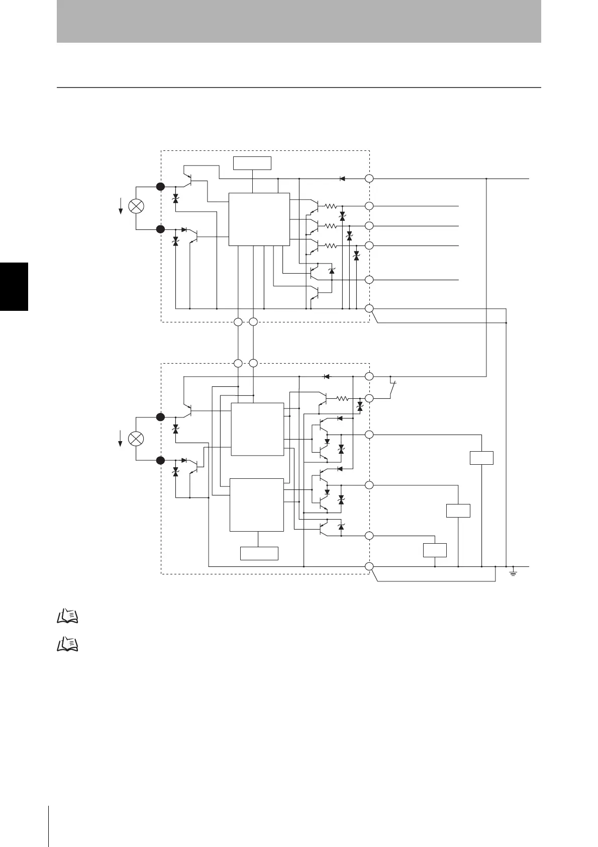
Input/Output Circuit
The numbers in white circles indicate the connector's pin numbers.
The black circles indicate connectors for series connection.
The words in brackets [ ] indicate the signal name for muting system.
For details about wiring, see the following sections.
When not using the muting function, see p.19
When using muting function, see p.29
Shield
Shield
+24V DC
0V
5
10
5
10
2
8
1
2
3
1
4
7
8
5
5
6
6
3
4
7
Emitter
Main Circuit
Indication
Receiver
Main Circuit 2
Communication line (-)
Pink
Grey
Grey
Pink
Communication line (+)
External indicator output 1
External indicator output 2
Brown
Green
Test input
White
[Muting input 1]
Red
[Muting input 2]
Reset input
Yellow
Yellow
Blue
Blue
Blue
Brown
Brown
Brown
Auxiliary output 1
Green
Safety output 1
Red
External device monitoring input
White Safety output 2
Blue
Load
Load
Load
Indication
Receiver
Main Circuit 1
Courtesy of CMA/Flodyne/Hydradyne ▪ Motion Control ▪ Hydraulic ▪ Pneumatic ▪ Electrical ▪ Mechanical ▪ (800) 426-5480 ▪ www.cmafh.com

 Loading...


