F
KM1
KM2
14
24
34
M
K3 K1 K3 K2
K1
K2
K3
K1 K2 K3
K3
E2E1D2D1C1
GND
Vcc
S1
+DC24V
0 V
E1
KM1
KM2
S2
Vcc
J1
A1 A2
T11 T12
H1
Y1
X1
13 23 33
GND
G1
T21
T22
KM1
KM2
ReceiverEmitter
Test
ReceiverEmitter
(Note 2)
Safety output Safety output
Master select
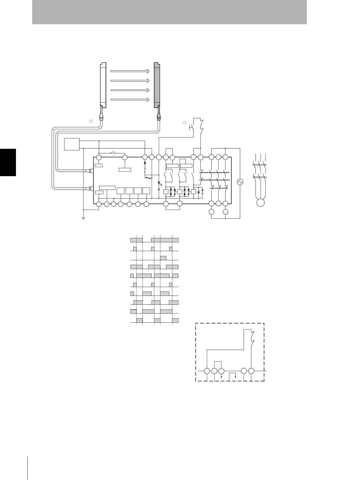
Model G9SA-300-SC
KM1,KM2 N.C. contact
Unblocked
Blocked
Interlock reset switch
(S1)
Safety output 1, 2
K1,K2 N.O. cotact
KM1,KM2 N.O. cotact
K1,K2 N.C. contact
External test switch
(S2)
K3 N.O. cotact
K3 N.C. contact
S1 :Interlock reset switch
S2 :External test switch
(open between Vcc and J1 if a switch is not required)
KM1, KM2 :Magnetic contactor
M :3-phase motor
E1 :24V DC power supply (S82K)
Note 1) F3SJ's external device monitoring and auxiliary output cannot be used.
Note 2) S2 performs normal operation when opened and external test when short-circuited.
Note 3) Do not connect any cable to terminals C1, D1, D2, E1, and E2
Model F39-JC C-L
Model F39-JC C-D
Sync
2-
Sync
2+
Sync
2-
Sync
2+
- F3SJ settings
- Not using external device monitoring
- G9SA-300-SC settings
- Manual reset mode
- Using feedback loop
Wiring for auto reset mode
X1
Y1
T11 T1 2
H1
KM1
KM2

 Loading...


