7
F3SJ-A
User’s Manual
Chapter1 Indicator Display Patterns
Overview and Specifications
E
Indicator Display Patterns
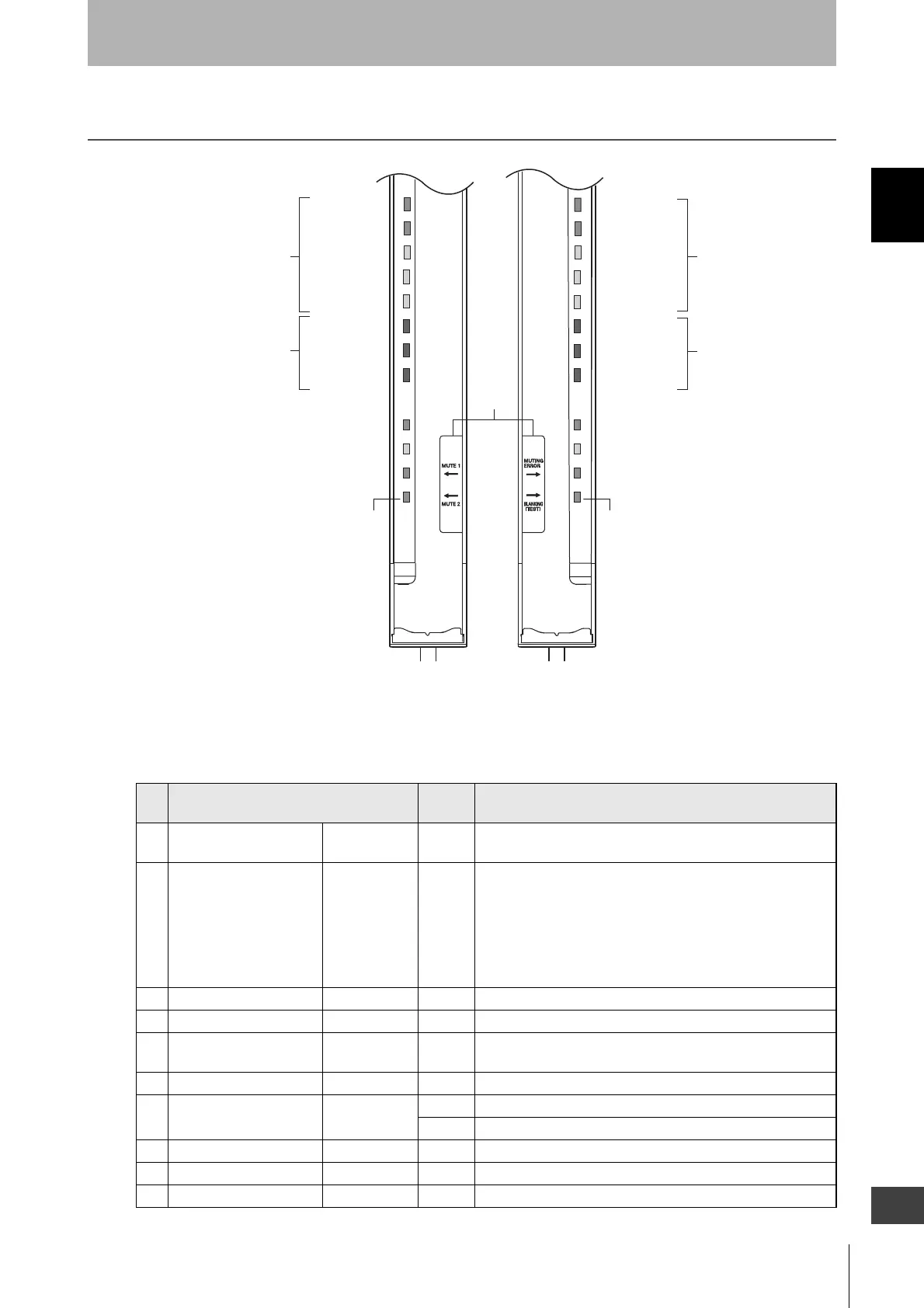
Internal Indicator for Basic System
Shown below are indication statuses of F3SJ's internal indicator when you purchased.
No. Indicators
ON/
Blinking
Description
1 Incident light level
indicator
LEVEL-1 to 5 ON Indication status of LEVEL-1 to 5 shows the incident light level
status of the F3SJ.
2 Error mode indicator ERROR-A to C ON/
Blinking
Turns ON or blinks only when the F3SJ enters lockout, and the
cause of the error is indicated by the status of ERROR-A to C
indicators.When F3SJ are series-connected, the error mode
indicator lamps turn ON or blink according to the details of each
error. Affix the error mode label (included) near the F3SJ to
allow for quick troubleshooting when errors occur. For details of
the error mode, see "Chapter 6 Troubleshooting".
3 Power indicator POWER ON Turns ON while the power is ON.
4 Lockout indicator LOCKOUT Blinking Blinks when in lockout.
5 External device
monitoring indicator
EDM ON Turns ON when an input is given to external device monitoring
input.
6 Test indicator TEST Blinking Blinks when external test is being performed.
7 OFF-state indicator OFF ON Turns ON when safety outputs are OFF.
Blinking Blinks when in lockout.
8 ON-state indicator ON ON Turns ON when safety outputs are ON.
9– – – –
10 – – – –
4. Lockout indicator (Yellow)
3. Power indicator (Green)
2. Error mode
indicator
1. Incident light level
indicator
EMITTER
LEVEL
POWER
ERROR ERROR
LOCKOUT
EDM
TEST
5
4
3
2
1
C
B
A
5
4
3
2
1
C
B
A
RECEIVER
LEVEL
OFF
ON
*1
LEVEL-5 (Green)
LEVEL-1 (Orange)
LEVEL-2 (Orange)
LEVEL-3 (Orange)
LEVEL-4 (Green)
ERROR-
C
(Red)
ERROR-B (Red)
ERROR-A (Red)
LEVEL-1 (Orange)
LEVEL-2 (Orange)
LEVEL-3 (Orange)
LEVEL-4 (Green)
LEVEL-5 (Green)
ERROR-B (Red)
ERROR-
A
(Red)
ERROR-C (Red)
1. Incident light
level indicator
2. Error mode
indicator
8. ON-state indicator (Green)
7. OFF-state indicator (Red)
Emitter Receiver
5. External device monitoring indicator (Green)
[Muting input 1 indicator]
6. Test indicator(Green)
[Muting input 2 indicator]
9. Not used (Green)
[Muting error indicator]
10. Not used (Green)
[Test indicator]
A set of square brackets, [ ], indicates
name of an indicator under muting system.
*1 This label comes with the F39-CN6 key
cap for muting. Affix this label when a
keycap is used.
Ǟ0
Ǟ20
Courtesy of CMA/Flodyne/Hydradyne ▪ Motion Control ▪ Hydraulic ▪ Pneumatic ▪ Electrical ▪ Mechanical ▪ (800) 426-5480 ▪ www.cmafh.com

 Loading...


