96
Chapter4 Wiring Examples
F3SJ-A
User’s Manual
Input/Output Circuit and Applications
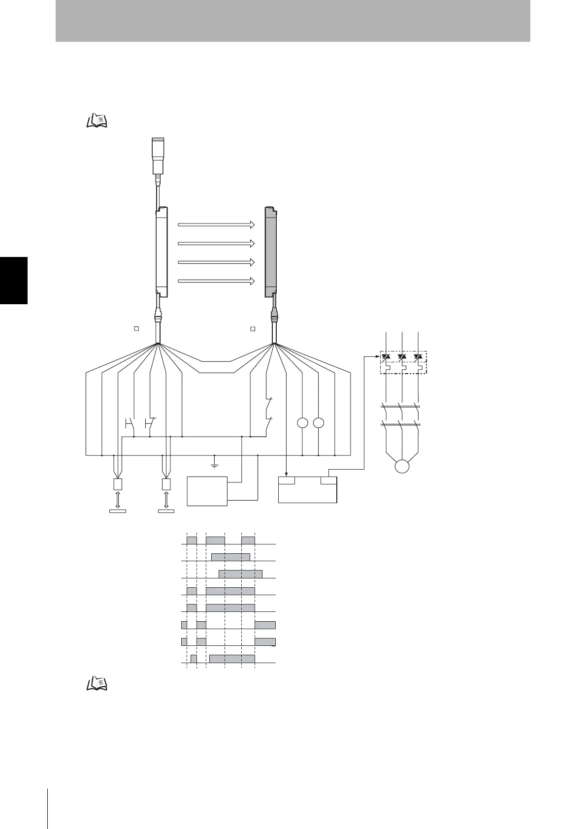
Connecting 2 Muting Sensors
• Attaching a key cap for muting (F39-CN6) enables the muting function to be used
Attaching the key cap for muting (F39-CN6) p.26
Wiring When External Device Monitoring Function Is Not Required p.29
F39-JC A-L
F39-JC A-D
OUT
PLC
IN
S1
S2
KM1
KM2
KM1
KM2
E1
+DC24V
0V
M
KM2
KM1
KM3
(PNP output)
Emitter Receiver
Communication
line (+) (Grey)
Communication
line (-) (Pink)
Shield
0V (Blue)
Muting input 2 (Red)
Test input (Green)
Reset input (Yellow)
Muting input 1 (White)
+24V (Brown)
Reflector
Muting sensor
+24V (Brown)
External device monitoring input (Red)
Auxiliary output 1 (Yellow)
Safety
output 1 (Green)
Safety
output 2 (White)
0V (Blue)
Shield
S1 :External test switch
(Short-circuit to 0V if the switch is not required)
S2 :Lockout reset switch
(Short-circuit to 24V if the switch is not required)
KM1, KM2 :Safety relay with forcibly-guided contact (G7SA) or
magnetic contactor
KM3 :Solid state contactor (G3J)
M :3-phase motor
E1 :24VDC power supply (S82K)
PLC :Programmable controller
(Used for monitoring -- not related to safety system)
Unblocked
Blocked
Muting input 1
Muting input 2
Safety output
KM1,KM2 N.O. contact
KM1,KM2 N.C. contact
PLC input
PLC output
- Using external device monitoring function
Muting lamp
(external indicator)
Muting sensor: Retro-reflective photoelectric sensor (E3Z-R81)
Courtesy of CMA/Flodyne/Hydradyne ▪ Motion Control ▪ Hydraulic ▪ Pneumatic ▪ Electrical ▪ Mechanical ▪ (800) 426-5480 ▪ www.cmafh.com

 Loading...


