S4
S1
IN1 IN2 OUT
PLC
KM3
M
KM1
KM2
E1
+DC24V
0V
A1 A2
T11 T12
S2
KM1
KM2
T31
K1
3
4
K2
1
a
b
2
5
T32
41332313
1
2
3
4
5
6
JP
6
a
b
K1
K2
K1
K2
PE T21
T23 T22
AB
14 24 34 42
Control
Circuit
KM1
KM2
*1
11
12
21
22
S3
Emitter Receiver
Shield
0V (Blue)
Open
Test input (Green)
Reset input (Yellow)
(White)
+24V (Brown)
Communication
line (+) (Grey)
Communication
line (-) (Pink)
+24V (Brown)
External devace monitoring input (Red)
Auxiliary output 1
(Yellow)
Safety output 1 (Green)
Safety output 2 (White)
0V (Blue)
Shield
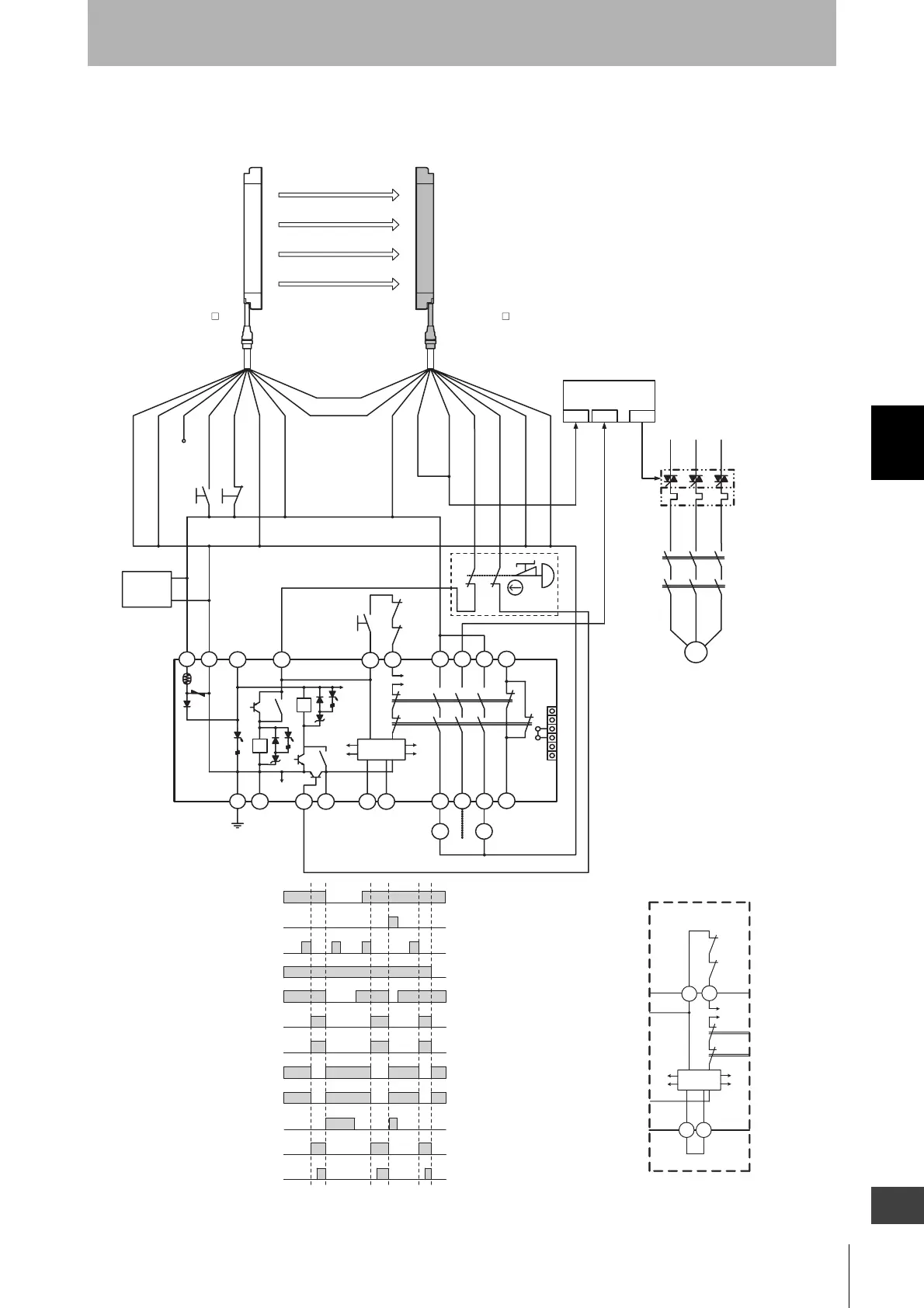
Model G9SA-301
Unblocked
Blocked
External test switch
(S1)
Interlock reset switch
(S2)
Emergency stop switch
(S3)
Control output
K1,K2 N.O. contact
KM1,KM2 N.O. contact
K1,K2 N.C. contact
KM1,KM2 N.C. contact
PLC input 1
PLC input 2
PLC output
S1 :External test switch
(Short-circuit to 0V if the switch is not required)
S2 :Interlock reset switch
S4 :Lockout reset switch
(Short-circuit to 24V if the switch is not required)
KM1, KM2 :Magnetic contactor
KM3 :Solid state contactor (G3J)
M :3-phase motor
E1 :24VDC power supply (S82K)
PLC :Programmable controller
(Used for monitoring -- not related to safety system)
- F3SJ settings
- Does not use external device monitoring function
- G9SA-301 settings
- Manual reset mode
- Using feedback loop
- Using emergency stop switch
*1 If an emergency stop switch is not used, connect safety
output 1 to T12 terminal and safety output 2 to T23 directly.
S3 : Emergency stop switch (forcibly-opening contact)
(A165E, A22E)
Model F39-JC A-L Model F39-JC A-D
(Red)
T32
T31
KM1
KM2
K1
K2
Control
Circuit
A B
Wiring for auto reset mode

 Loading...


