A1
A2
S14 S24
KM1 KM2
S34 S44 S54
KM3 KM4
L1 X1 X2
T11
KM1
KM2
KM3
KM4
+24V +24V
T12 T21 T22 T31 T32 T33 Y1 T41 T42
M1 M2
PLC, etc.
Motor controller
OFF
AND
KM1
KM2
KM3
S34
KM4
Control circuit
S1
S2
F39-JC A-L F39-JC A-D
+DC24V
0V
E1
Feedback loop
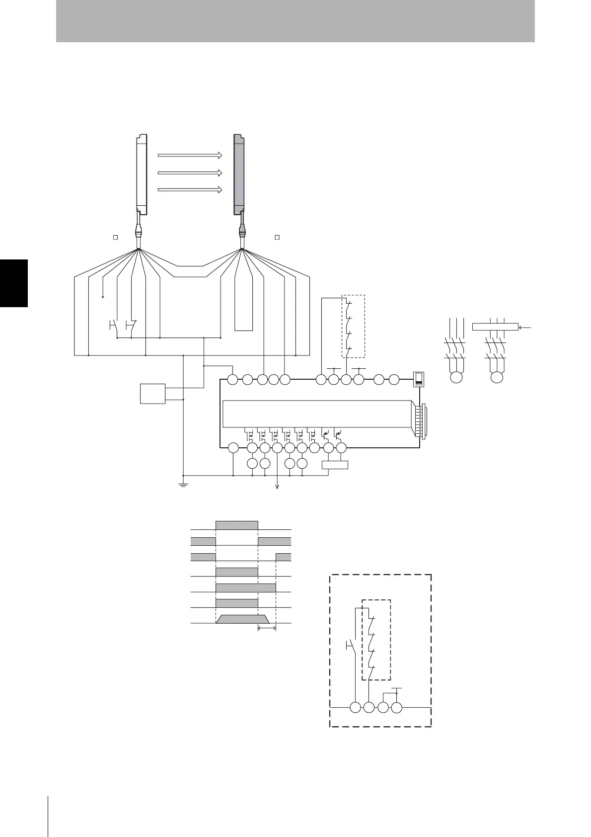
- F3SJ settings
- Not using external device monitoring
- G9SX-AD322-T15 settings
- Auto reset mode
- Using feedback loop
Emitter
Receiver
Motor controller
(operation command)
Model G9SX-AD322-T15
Open
Open
Open Open
Safety sensor safety output
KM1,KM2 N.C. contact
KM3,KM4 N.C. contact
KM1,KM2 N.O. contact
KM3,KM4 N.O. contact
Motor operation command
Motor rotation
OFF-delay time
Shield
0V (Blue)
Open
Test input (Green)
Reset input (Yellow)
(White)
+24V (Brown)
Communication
line (+) (Grey)
Communication
line (-) (Pink)
+24V (Brown)
External devace monitoring input (Red)
Auxiliary output 1 (Yellow)
Safety output 1 (Green)
Safety output 2 (White)
0V (Blue)
Shield
S1 :External test switch
(Short-circuit to 0V if the switch is not required)
S2 : Lockout reset switch
(Short-circuit to 24V if the switch is not required)
KM1~KM4 :Magnetic contactor
M1, M2 : 3-phase motor
E1 :24VDC power supply (S82K)
PLC :Programmable controller
(Used for monitoring -- not related to safety system)
(Red)
+24V
T32 T33
Y1
KM3
KM4
T31
KM1
KM2
S3
Wiring for manual reset mode
Feedback loop
S3 : R
eset switch

 Loading...


