57
F3SJ-A
User’s Manual
Chapter3 Attaching External Indicators
Wiring/Installation
E
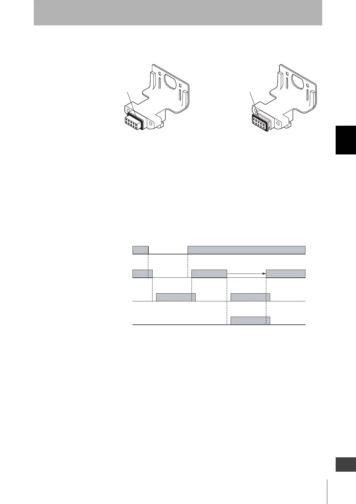
- Attaching/detaching of a cap or a series-connection cable may cause misalignment of rubber grommet in a connector
assembly.
Press the grommet to the bottom of the connector and attach the connector F3SJ again.
Output Operation
The external indicator output 1 (on the receiver side) is configured as "safety output reverse output
(ON when blocked)", while the external indicator output 2 (on the emitter side) is configured as "lockout
output (ON during lockout)".
When the muting function is used, both the emitter and receiver are configured as muting/override
output (Blinking during muting and during override).
Timing chart of basic system
Rubber Grommet Rubber Grommet
Rubber Grommet in Right Position Misaligned Grommet
Safety output
ON
OFF
ON
OFF
ON
OFF
Unblocked
/Blocked
Unblocked
Blocked
Lockout
External indicator output 1
External indicator output 2
( Receiver )
( Emitter )
Courtesy of CMA/Flodyne/Hydradyne ▪ Motion Control ▪ Hydraulic ▪ Pneumatic ▪ Electrical ▪ Mechanical ▪ (800) 426-5480 ▪ www.cmafh.com

 Loading...


