EasyManuals Logo

Omron F3SJ-A series User Manual

Omron F3SJ-A series
148 pages
To Next Page IconTo Next Page
To Previous Page IconTo Previous Page
Page #116 background imageLoading...
Page #116 background image
98
Chapter4 Wiring Examples
F3SJ-A
User’s Manual
Input/Output Circuit and Applications
Connecting to an F3SP-B1P
•Reduced wiring due to connector connection
•Safety relay included
It cannot be used as a muting system when F3SP-B1P is used.
Muting System p.25
T32T31
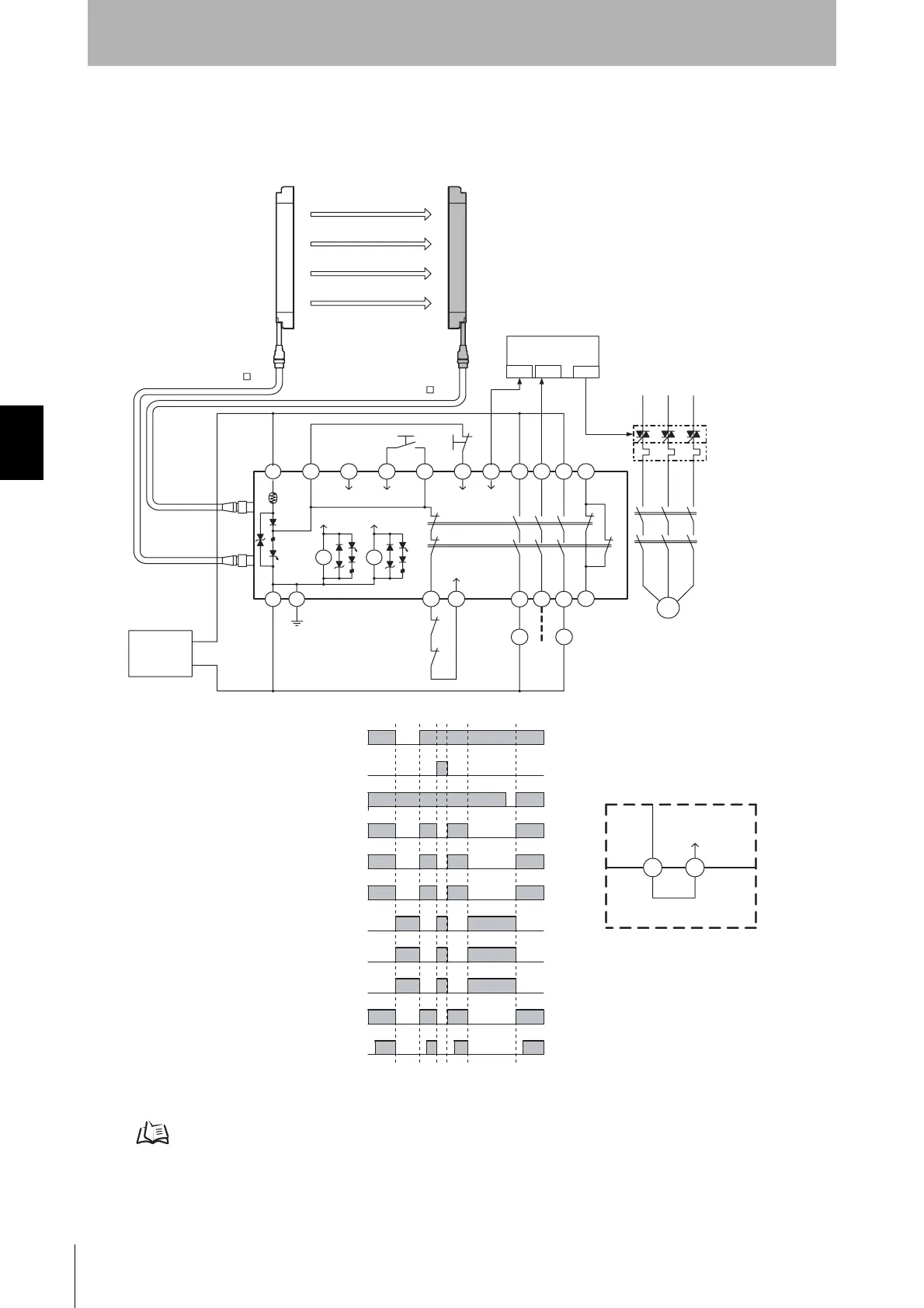
Wiring when not using external device
monitoring function
External device
monitoring
Standard short-circuit bar
PLC
IN1 IN2 OUT
S1
S2
A1 H1 L1 J1 H1 X1 P1 13 23 33 41
KM3
KM1
KM2
Safety
Output1
Safety
Output2
K1
K2
K1 K2
A2 PE T31 T32
14 24 34 42
KM1
KM2
KM1
KM2
E1
+DC24V
0V
M
Emitter
Receiver
Test
Reset
Auxiliary
output
External device
monitoring
Model F3SP-B1P
- Using external device monitoring function
S1 :External test switch
S2 :Lockout reset switch
KM1, KM2 :Magnetic contactor
KM3 :Solid state contactor (G3J)
M :3-phase motor
E1 :24VDC power supply (S82K)
PLC :Programmable controller
(Used for monitoring not related to safety system)
Model F39-JC B-L
Model F39-JC B-D
Unblocked
Blocked
External test switch (S1)
Reset switch (S2)
Safety output
K1,K2 N.O. contact
KM1,KM2 N.O. contact
K1,K2 N.C. contact
KM1,KM2 N.C. contact
PLC input 1
PLC input 2
PLC output
Lockout
state
Courtesy of CMA/Flodyne/Hydradyne Motion Control Hydraulic Pneumatic Electrical Mechanical (800) 426-5480 www.cmafh.com

Table of Contents

Other manuals for Omron F3SJ-A series

Questions and Answers:

Question and Answer IconNeed help?

Do you have a question about the Omron F3SJ-A series and is the answer not in the manual?

Omron F3SJ-A series Specifications

General IconGeneral
BrandOmron
ModelF3SJ-A series
CategoryAccessories
LanguageEnglish

Related product manuals