catalogs.
OUT
PLC
KM1
KM2
IN1 IN2
KM3
A1
14
24
34
42
41332313
T32
T31
T11
A2
G9SB-301-D
KM1
KM2
T12
K1
K1
K2
K1
S2
S1
a
K2
Control
Circuit
a
T21
T22
K2
K2
K1
F39-JC A-L
F39-JC A-D
TH
SA
+DC24V
0V
E1
*1*1
*1*1
M
*2
12
21
22
S3
KM1
KM2
Emitter Receiver
Shield
0V (Blue)
Open
Test input (Green)
Reset input (Yellow)
(White)
+24V (Brown)
Communication
line (+) (Grey)
Communication
line (-) (Pink)
+24V (Brown)
External devace monitoring input (Red)
Auxiliary output 1 (Yellow)
Safety output 1 (Green)
Safety output 2 (White)
0V (Blue)
Shield
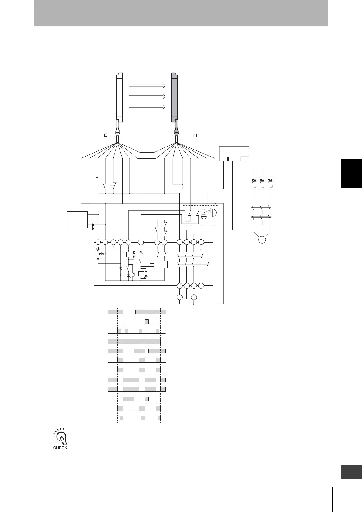
Unblocked
Blocked
External test switch
(S1)
Interlock reset switch
(S2)
Emergency stop switch
(S3)
Safety output1, 2
K1,K2 N.O. contact
KM1,KM2 N.O. contact
K1,K2 N.C. contact
KM1,KM2 N.C. contact
PLC input 1
PLC input 2
PLC output
S1 :External test switch (Short-circuit to 0V if the switch is not required)
S2 :Interlock reset switch
S4 :Lockout reset switch (Short-circuit to 24V if the switch is not required)
KM1, KM2 :Magnetic contactor
KM3 :Solid state contactor (G3J)
M :3-phase motor
E1 :24VDC power supply (S82K)
PLC :Programmable controller
(Used for monitoring -- not related to safety system)
- F3SJ settings
- Does not use external device monitoring function
- G9SB-301-D settings
- Manual reset mode
- Using feedback loop
*1 The G9SB-200-D (17.5 mm thick), with no 33-34 and 41-42, is also available.
S3
: Emergency stop switch (forcibly-opening contact)
(A165E, A22E)
*2 If an emergency stop switch is not used, connect safety output 1 to T12
terminal and safety output 2 to T22 directly.
S4
(Red)

 Loading...


