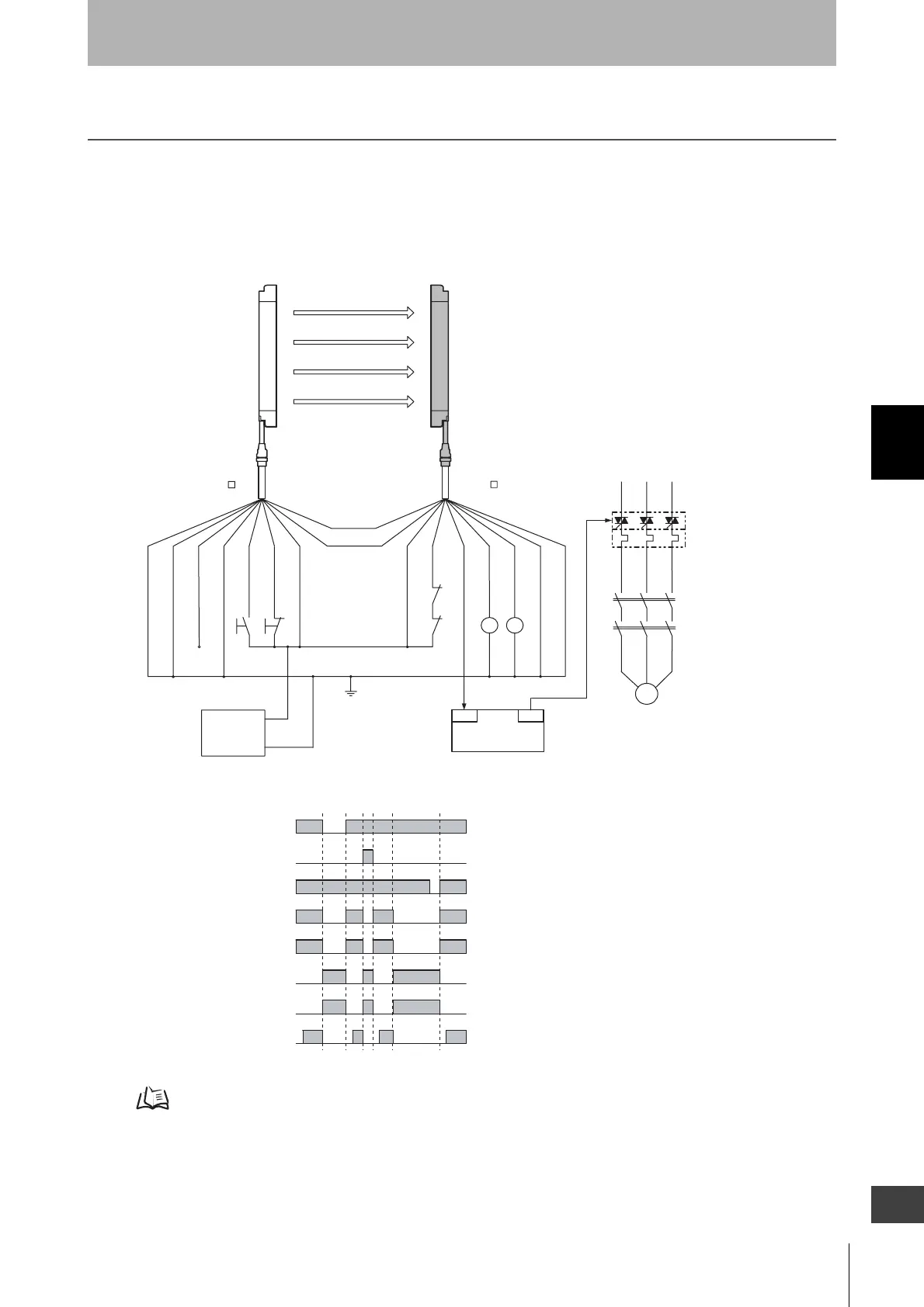
OUT
PLC
IN
S1
S2
KM1
KM2
KM1
KM2
E1
+DC24V
0V
M
KM2
KM1
KM3
F39-JC A-L
F39-JC A-D
Emitter Receiver
Communication
line (+) (Grey)
Communication
line (-) (Pink)
Shield
0V (Blue)
(Red)
(White)
OPEN
Test input (Green)
Reset input (Yellow)
+24V (Brown)
+24V (Brown)
External device monitoring input (Red)
Auxiliary output 1 (Yelllow)
Safety
output 1 (Green)
Safety
output 2 (White)
0V (Blue)
Shield
S1 :External test switch
(Short-circuit to 0V if the switch is not required)
S2 :Lockout reset switch
(Short-circuit to 24V if the switch is not required)
KM1, KM2 :Safety relay with forcibly-guided contact (G7SA) or
magnetic contactor
KM3 :Solid state contactor (G3J)
M :3-phase motor
E1 :24VDC power supply (S82K)
PLC :Programmable controller
(Used for monitoring -- not related to safety system)
- Using external device monitoring function
Unblocked
Blocked
External test switch (S1)
Reset switch (S2)
Safety output
KM1,KM2 N.O. contact
KM1,KM2 N.C. contact
PLC input
PLC output
Lockout
state

 Loading...


