S1
S2
11
12 22
21
DC24V
E1
A1 T11 T12 T21 T22 Y1 Y2 Y3
DC24V
E1
A2
DC24V
DC24V
COM
0V
SSC AS3 AS2 AS1 SS1 SS2 FB
E1
DC24V
RY1 RY2
DC24V
E1
KM1
KM2
M
RY1
RY2
15 1012131416911
2
7
543186
12 3424
3311 23
AC
K1
K2
KM1 KM2
27543186
15 1012131416911
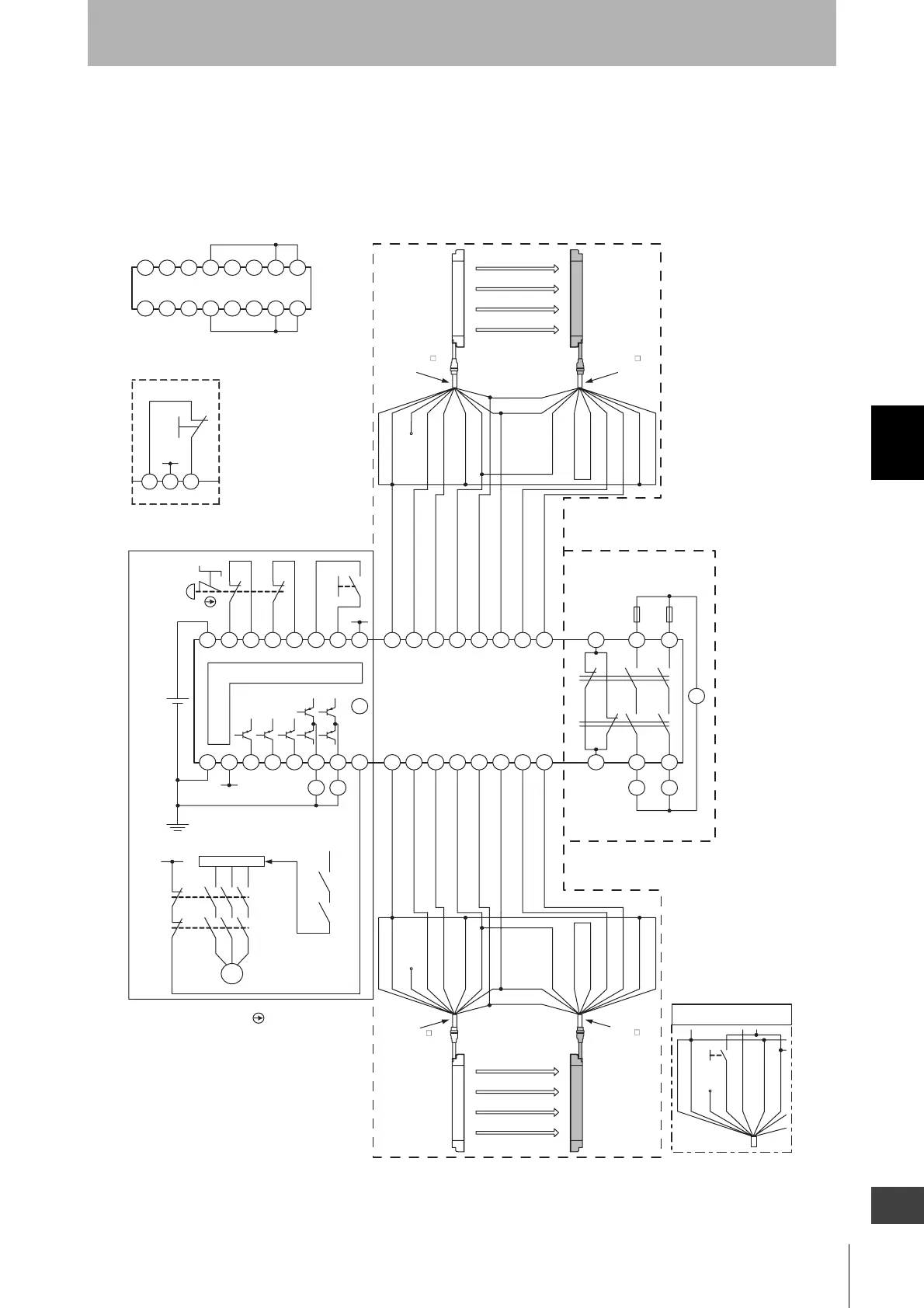
Wiring when safety light curtain
F3SJ is not used
L2 Module
Emitter Receiver
F3SJ (1st unit)
Communication
line (+) (Grey)
Communication
line (-) (Pink)
Shiel
0V (Blue)
Open
Test input (Green)
Reset input (Yellow)
(White)
+24V (Brown)
+24V (Brown)
External device monitoring
input (Red) (Note 2)
Auxiliary output 1
(Yellow) (Note 2)
(Red)
Safety output 1 (Green)
Safety output 2 (White)
0V (Blue)
Shield
Main Module
Control Circuit
Motor controller
(operation command)
S1 :Emergency stop switch
(direct circuit operation contact)(A165E, A22E)
S2 :Reset switch
KM1, KM2 :Magnetic contactor (LC1D)
RY1, RY2 :Relay
M :3-phase motor
E1 :24VDC power supply (S82K)
Note 1. This wiring example is for category 4.
Shield
0V (Blue)
DC24V (Brown)
DC24V (Brown)
0V (Blue)
Shield
Test input (Green)
Reset input (Yellow)
(White)
Open
External device monitoring
input (Red) (Note 2)
Auxiliary output 1 (Yellow)(Note 2)
(Red)
Safety
output 1 (Green)
Safety
output 2 (White)
Communication
line (+) (Grey)
Communication
line (-) (Pink)
F3SJ (2nd unit)
Emitter Receiver
Shield
Test SW
0V (Blue)
Open (Red)
Test input (Green)
Reset input (Yellow)
(White)
DC24V (Brown)
Wiring when F3SJ's
testing function is used
Relay Output Module
(R Module)
Fuse
- F3SJ settings
- Does not use external device monitoring function
- F3SX-E-L2R settings
- Manual reset mode
- Using feedback time monitoring function
Note 2. When the F3SJ is series-connected, or 5 or more sets
are connected to the total system of F3SX, power
must be supplied to F3SJ from external source.
For details, see documentation of F3SX.
Model F39-JC A-L
cable for emitter
Model F39-JC A-D
cable for receiver
Model F39-JC A-L
cable for emitter
Model F39-JC A-D
cable for receiver
Y3Y2Y1
E1
DC24V
S2
Wiring for auto reset mode

 Loading...


