27
F3SJ-A
User’s Manual
Chapter2 Muting System
System Configuration and Functions
E
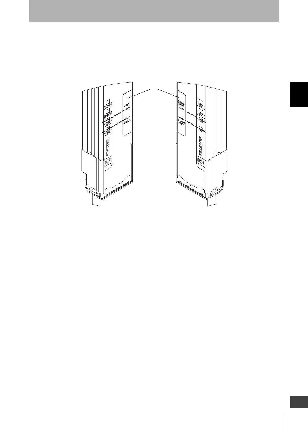
• Where to attach the included labels
F39-CN6 key cap for muting includes internal indicator label (1).
When muting system is used, affix the label (1) in a location so that the arrows are aligned with the
portion of the internal indicator display indicated by the shaded zones.
Standard Muting Mode
Turning muting inputs 1 and 2 ON with time difference enables muting function.
Start Conditions
If both of the following 2 conditions are present for the F3SJ, muting is activated.
1. No interrupting object is found in the F3SJ's detection zone, and safety outputs are ON.
2. After muting input 1 is turned ON (connected to 9 to 24V), muting input 2 is turned ON (connected to
9 to 24V) within the muting input time limit of T1min to T1max (0.03 to 3s).
Muting function can be enabled in up to 0.15s
*1
after the condition 2 is satisfied. If condition 1 is
satisfied but the time requirement of condition 2 is not, a muting error occurs, and the receiver's muting
error indicator turns ON. However, when there is a muting error, the F3SJ safety function operates and
normal operation continues.
Muting error can be released by any of following conditions:
•When muting is started by the proper muting sequence (start conditions 1 and 2 are performed in
order).
•Power cycle under muting input 1 and 2 OFF state.
Emitter
Receiver
(1)
Courtesy of CMA/Flodyne/Hydradyne ▪ Motion Control ▪ Hydraulic ▪ Pneumatic ▪ Electrical ▪ Mechanical ▪ (800) 426-5480 ▪ www.cmafh.com

 Loading...


