20
Chapter2 Basic System
F3SJ-A
User’s Manual
System Configuration and Functions
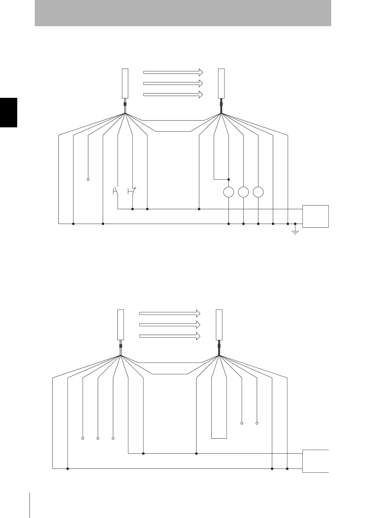
Wiring When External Device Monitoring Function Is Not Used
The external device monitoring function is disabled by connecting auxiliary output 1 and external
device monitoring input as shown below.
Ref.: Minimum Wiring Required to Check the Operation of the F3SJ
(Wiring for deactivated external device monitoring function)
Power
supply
S1 S2
*1
*1
*2
K3 K1 K2
0V
S1
S2
K1, K2
K3
: External test switch (connect to 0V if a switch is not required)
: Lockout reset switch (connect to 24V if a switch is not required)
: Relay or other device that controls hazardous parts of the machine
: Load or PLC, etc. (for monitoring)
*1 Use a switch for micro loads (Input specifications: 24V, 1.8mA)
*2 F3SJ can operate even if K3 is not connected. If K3 is not required, connect auxiliary output 1 to external device
monitoring input only.
(White)
0V(Blue)
0V(Blue)
Shield
Shield
Test input(Green)
Reset input(Yellow)
24V(Brown)
24V(Brown)
External device monitoring input (Red)
Auxiliary output 1(Yellow)
Safety output 1(Green)
Safety output 2(White)
(Red)
+24V DC
Open
(Grey) Communication line (+)
(Pink)
Communication line (-)
Emitter
Receiver
Open
Open
Open
Open
Open
+24V DC
0V
(White)
Emitter
Receiver
(Grey) Communication line (+)
(Pink)
Communication line (-)
0V(Blue)
0V(Blue)
Power
supply
Shield
Shield
Test input(Green)
Reset input(Yellow)
24V(Brown)
24V(Brown)
External device monitoring input (Red)
Auxiliary output 1(Yellow)
Safety output 1(Green)
Safety output 2(White)
(Red)
Courtesy of CMA/Flodyne/Hydradyne ▪ Motion Control ▪ Hydraulic ▪ Pneumatic ▪ Electrical ▪ Mechanical ▪ (800) 426-5480 ▪ www.cmafh.com

 Loading...


