30
Chapter2 Muting System
F3SJ-A
User’s Manual
System Configuration and Functions
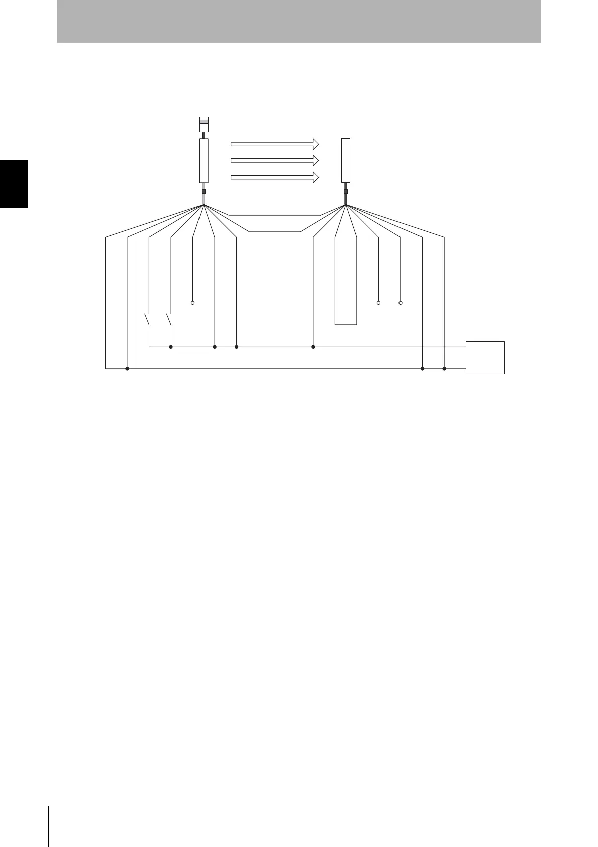
Ref.: Minimum Wiring Required to Check the Operation of the F3SJ When Using the
Muting Function
(Wiring that does not use the external device monitoring function)
Open
Open
Open
A1B1
*1*1
M1 *1 *2
+24V DC
0V
A1 : Contact by muting sensor A1
B1 : Contact by muting sensor B1
M1 : Muting lamp
Muting input 1 (White)
Muting input 2 (Red)
*1
When the muting function's operation check is not performed, it can work if this is open.
*2 Connect either the emitter or receiver to the muting lamp.
Emitter
Receiver
(Grey) Communication line (+)
(Pink) Communication line (-)
0V(Blue)
0V(Blue)
Power
supply
Shield
Shield
Test input(Green)
Reset input(Yellow)
24V(Brown)
24V(Brown)
External device
monitoring input (Red)
Auxiliary output 1(Yellow)
Safety output 1(Green)
Safety output 2(White)
Courtesy of CMA/Flodyne/Hydradyne ▪ Motion Control ▪ Hydraulic ▪ Pneumatic ▪ Electrical ▪ Mechanical ▪ (800) 426-5480 ▪ www.cmafh.com

 Loading...


