37
F3SJ-A
User’s Manual
Chapter2 Muting System
System Configuration and Functions
E
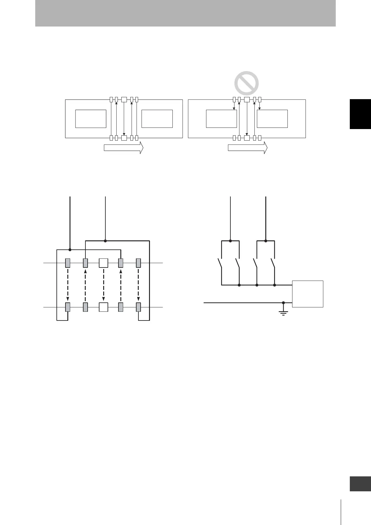
This distance must prevent the muting function from being enabled by a person passing through the
muting sensors. Also, install the F3SJ and muting sensors so that a workpiece passes through all
muting sensors before the next workpiece arrives at the first muting sensor.
Wiring Diagrams
Workpiece Workpiece Workpiece Workpiece
Moving direction Moving direction
+24V DC
0V
A2A1 B2B1
A2
A1 B2
B1
F3SJ
Muting Input 1
(White)
Muting Input 1
(White)
Muting Input 2(Red)
Muting Input 2(Red)
Power
supply
Using a photoelectric switch as a muting sensor Using an N.O contact type switch as a muting sensor
A1, B1, A2, B2 :
Regressive reflection
photoelectric switch
- PNP Output
- ON when Interrupted
A1, A2, B1, B2:
N.O contact type switch
Courtesy of CMA/Flodyne/Hydradyne ▪ Motion Control ▪ Hydraulic ▪ Pneumatic ▪ Electrical ▪ Mechanical ▪ (800) 426-5480 ▪ www.cmafh.com

 Loading...


