39
F3SJ-A
User’s Manual
Chapter2 Muting System
System Configuration and Functions
E
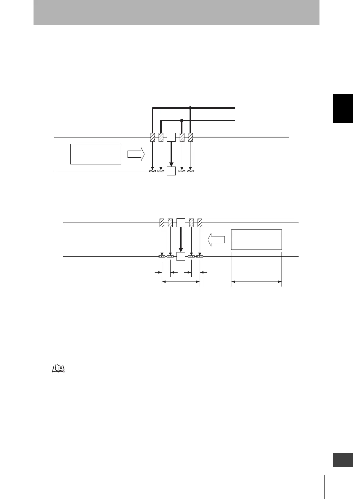
Reference: Bidirectional Muting
Shown below is an example of bidirectional muting with 4 retro-reflective photoelectric sensors.
It can be used for applications of workpiece approaching from both directions.
Connect outer muting sensors A1 and A2 to the muting input 1 and inner muting sensors B1 and B2 to
the muting input 2.
1. Workpiece approaching from the left
2. Muting from an opposite direction is available as well
This arrangement example uses regressive reflection type E3Z-R series as a muting sensor.
Arrangement must take mutual interference into account.
Muting sensors must be installed so that a distance D3 between muting sensors A1 and A2 should be
smaller than workpiece length L.
As a muting sensor, a transmission or regressive reflection type photoelectric switch, proximity switch,
or limit switch can be used.
Distances d2 & D2 between muting sensors: p.36
V
F3SJ
A1 B1 B2 A2
Connect to muting Input 1
Connect to muting Input 2
Turning muting sensors ON in an order from
A1 to B1 sets F3SJ to a muting status.
Workpiece
A1, A2, B1, B2: Retro-reflective photoelectric senso
V
D3 L
A1 B1 B2 A2
F3SJ
d2 d2
Workpiece
Turning muting sensors ON in an order from
A2 to B2 sets F3SJ to a muting status.
Courtesy of CMA/Flodyne/Hydradyne ▪ Motion Control ▪ Hydraulic ▪ Pneumatic ▪ Electrical ▪ Mechanical ▪ (800) 426-5480 ▪ www.cmafh.com

 Loading...


