60
Chapter3 Dimensions
F3SJ-A
User’s Manual
Wiring/Installation
Dimensions A to E
Dimension E
*1. Use E = 530 or less when none of the E values shown above are used.
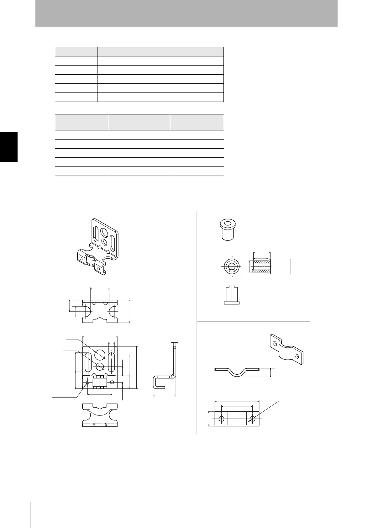
Dimensions of Standard Brackets (top/bottom mounting brackets)
AC + 74
B C + 46.5
C 4-digit number of the model name (protective height)
DC - 20
E Depends on the protective height. See the table below.
Protective height
Number of intermediate
mounting brackets
E*1
0245 to 0596 0 -
0600 to 1130 1 B/2
1136 to 1658 2 B/3
1660 to 2180 3 B/4
2195 to 2500 4 B/5
16
2
30
19.6
21
10
9
19.6
8
18
11
5.5
36.5
16.5
14.5
13.5
A-A
A
A
11.5
21
30
10
2-M3
Through holes
(Unit: mm)
Material: Stainless steel
Material: Stainless steel
Material: Brass
5.6
5.5
dia. 9
dia. 6.5
2-dia. 3.5
Courtesy of CMA/Flodyne/Hydradyne ▪ Motion Control ▪ Hydraulic ▪ Pneumatic ▪ Electrical ▪ Mechanical ▪ (800) 426-5480 ▪ www.cmafh.com

 Loading...


