76
Chapter3 Dimensions
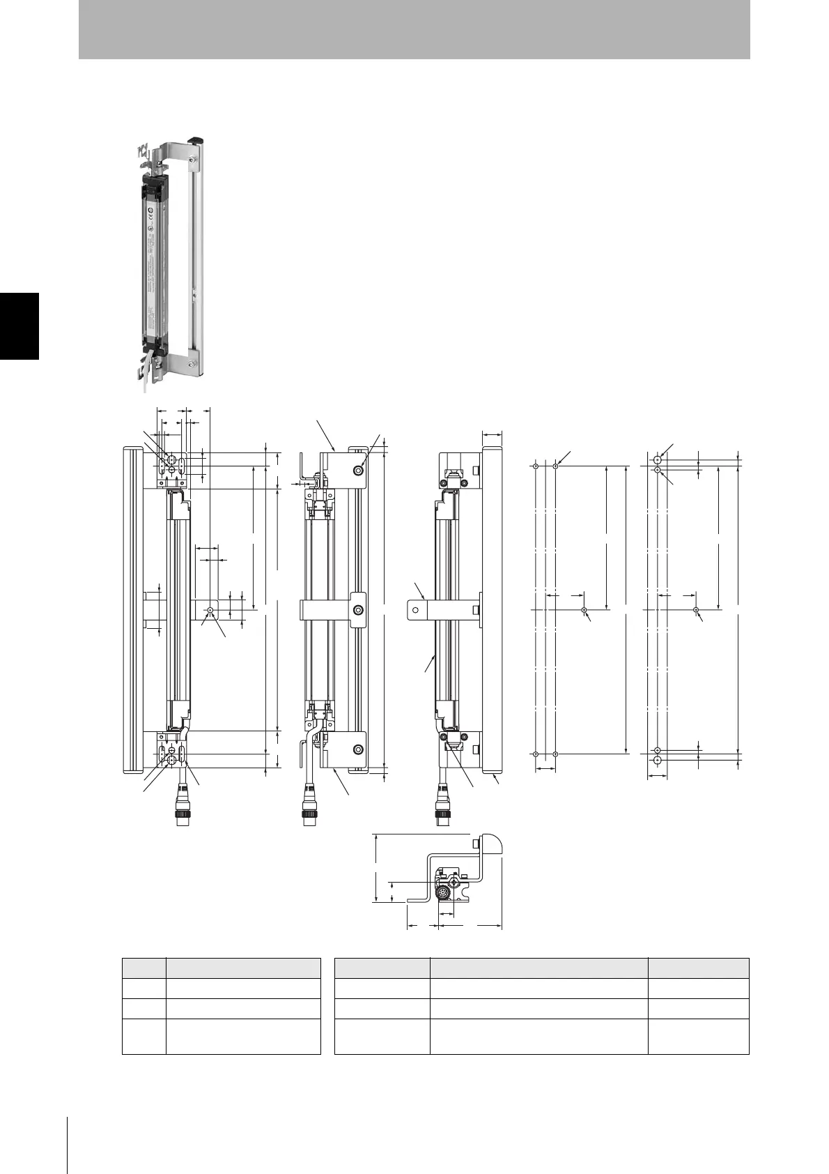
F3SJ-A
User’s Manual
Wiring/Installation
Dimensions A to C Dimension D
Protective height Number of used protection brackets (4) D *2
A C+74 245 to 1000 0 -
B C+46.5 1001 to 2000 1 B/2
C 4-digit number of the model
name (protective height)
2009 to 2495 2 B/3
*2 D is for reference and must be a length that should not affect intermediate mounting bracket
16.5
4
5.5
AB
10 20
36
D
69
6432
15
(6)
20
20
20
30 24
8
23
5
B
M5
39
D
6.25
20
2-M8
2-M6
3.75
3.75
6.25
B
M5
39
D
20
4-M5
(37)
(37)
(13.75)
(13.75)
dia.5.5
(6)
dia.9
dia.6.5
Side mounting
C
(Protective
height)
Hole size for mounting
Protection
Bracket (4) *1
Protection Bracket (2)
Protection Bracket (1)
Mounting hole
(Unit: mm)
Using M5 Using M6 and M8
3-M5
Hex. Bolt
with Washer and Hole
Sensor
4-Mounting holes
2-Mounting holes
2-Mounting holes
Protection Support
Material: Stainless steel and aluminum
4-M3
Hex. Bolt
with Washer and Hole
*1 Protection Bracket (4) (F39-PJ-MS)
is not included.
Courtesy of CMA/Flodyne/Hydradyne ▪ Motion Control ▪ Hydraulic ▪ Pneumatic ▪ Electrical ▪ Mechanical ▪ (800) 426-5480 ▪ www.cmafh.com

 Loading...


