Precautions for Correct Use
• When you execute Non-stop data transfer, the results in the Trend Monitor and
Expression processing units are cleared.
• If you use an external command to switch scenes or scene groups, or change the settings of
processing units while the Controller is in RUN mode, the results of those changes will not be
applied when you change to line 1 (Adjustment Mode) in the Main Window.
• If you use the Non-stop Adjustment Mode after you change the scene group while the Con-
troller is in RUN mode, you may overwrite the scene group data unintentionally.
• The only communications commands that are accepted during a non-stop data transfer are
the measurement (parallel, non-procedure, or PLC Link) and continuous measurement (par-
allel only) commands.
• The larger the size of the scene group file, the longer the non-stop data transfer will take.
• The communications settings cannot be changed in Non-stop Adjustment Mode.
• Do not register a new Camera Image Input processing unit in the Non-stop Adjustment Mode
Window.
• If there is not enough RAMDisk space, the Nonstop data transfer may not perform.
Set the external storage device to save the Image logging, keep the RAMDisk space.
• Do not change the image mode for Non-stop Adjustment Mode.
• If you use image logging in Non-stop Adjustment Mode, the non-stop data transfer may be-
come unavailable. To avoid this, set the trigger frequency so that it is longer than the logging
time.
• Do not change the settings for image input processing items and do not change Camera pa-
rameters in the system settings in Non-stop Adjustment Mode.
Do not make the following changes when using Non-stop Adjustment Mode.
a) Setting changes in Image Input related processing items
b) Camera parameter changes in System setting
c) Changes in loaded scene data and system data, including the parameters described in a)
and b) above
• Do not select Transfer data during Line1 while Non-stop Adjustment Mode Window is run-
ning. You cannot measure during data transfer. Make sure to set Transfer data before run-
ning.
• When Parallel Execute in Operation mode setting of System setting is ON, the measure-
ment time might be longer since the Parallel processing effect is reduced.
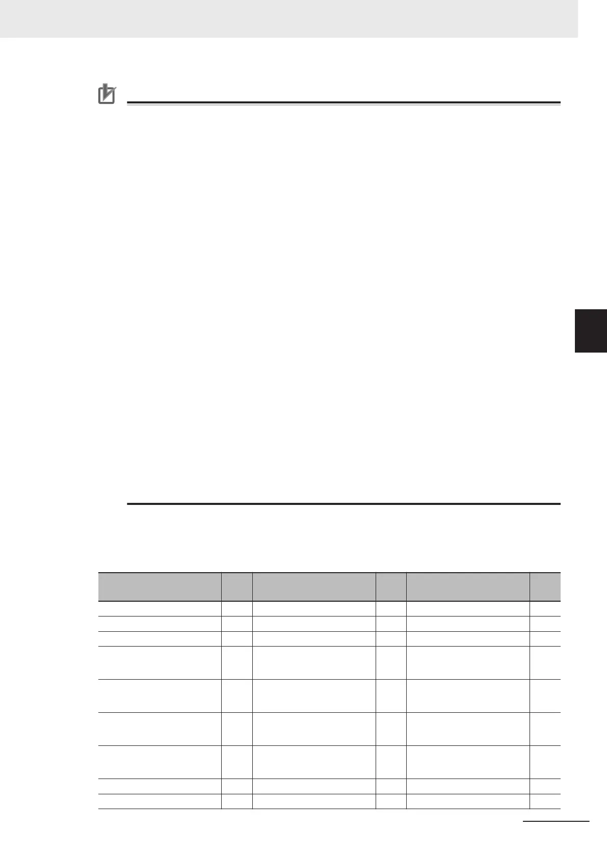
The following processing items are supported in Non-Stop Adjustment Mode:
OK:Supported processing item, RST: Processing item with restricted support,
-:Unsupported processing item
Processing item
Sup-
port
Processing item
Sup-
port
Processing item
Sup-
port
Camera Image Input - Extract Color Filter OK Conditional Branch OK
Camera Image Input FH - Anti-Color Shading OK End OK
Camera Image Input FHV - Stripes Removal Filter II OK DI Branch -
Camera Image Input HDR - Polar Transformation OK Control Flow Normal
RST
*
3
Camera Image Input HDR
Lite
- Trapezoidal Correction OK Control Flow PLC Link
RST
*
3
Camera Switching OK Machine Simulator OK Control Flow Parallel
RST
*
3
Measurement Image
Switching
OK Image Subtraction
RST
*
2
Control Flow Fieldbus
RST
*
3
Search OK Advanced Filter OK Selective Branch OK
Flexible Search OK Panorama OK Data Output OK
4 Setting the Controller
4 - 25
FH/FHV Series Vision System User’s Manual (Z365-E1)
4-4 Setting Operation Mode [Startup Settings]
4
4-4-1 Setting the Operation Mode
 Loading...


