Outputting Data and Controlling Operation through EtherNet/IP
FQ2 User’s Manual
303
Connecting through Ethernet
9
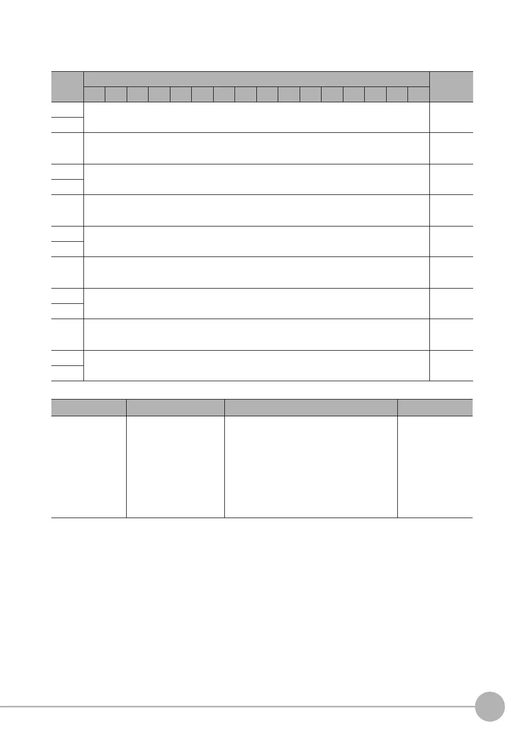
• Output Area
The output area is assigned immediately after the response area in I/O memory.
Bits Contents
15 14 13 12 11 10 9 8 7 6 5 4 3 2 1 0
+8
DATA 0
Output data
0 (32 bits)
+9
·
·
·
·
·
·
·
·
·
+22
DATA 7
Output data
7 (32 bits)
+23
·
·
·
·
·
·
·
·
·
+38
DATA 15
Output data
15 (32 bits)
+39
·
·
·
·
·
·
·
·
·
+70
DATA 31
Output data
31 (32 bits)
+71
·
·
·
·
·
·
·
·
·
+134
DATA 63
Output data
63 (32 bits)
+135
Signal Signal name Function Application
DATA0-63 Output data 0 to 63 These I/O ports output the output data that is
specified for the data output method.
The data that can be output is determined by
the set value of the Output data size setting as
follows:
32 bytes: Output data 0 to 7
64 bytes: Output data 0 to 15
128 bytes: Output data 0 to 31
256 bytes: Output data 0 to 63
Command/
response commu-
nications