Wiring
FQ2 User’s Manual
2
Installation and Connections
49
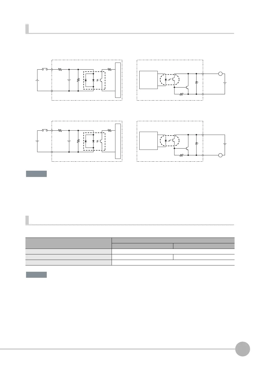
I/O Signal Circuit Diagrams
Preventing Chattering
• The Sensor is equipped with an anti-chattering function, but if the chattering is 100 μs or longer, a faulty input may
occur. (Input signals of 99 μs or shorter are ignored. Signals of 100 μs or longer are treated as input signals.)
• Use no-contact output devices (e.g., SSR or PLC transistor output) for the input signals. If contacts (e.g., a relay)
are used, chattering may cause the trigger to be input again during execution of a measurement.
Power Supply Specifications When a Switching Regulator Is Connected
Use a power supply that meets the following specifications. (They are sold separately.)
Supply power from a DC power supply for which measures have been applied to prevent high voltages (e.g., a safety
extra-low-voltage circuit).
If UL certification is required for the overall system, use a UL Class II DC power supply.
NPN
PNP
Item Description
FQ2-S2@@@@@@@ connection FQ2-S3@-@ connection
Power supply voltage 24 VDC (21.6 to 26.4 V)
Recommended Power Supplies S8VS-06024@ (24 VDC, 2.5 A) S8VS-03024 (24 VDC, 1.3 A)
External power supply terminal screws M4 (tightening torque: 1.2 N·m)
3 KΩ
910 Ω
1000 pF
COM_I
Input terminal
+
Input Circuit
Internal circuits
Output terminal
Load
Output Circuit
L
COM_O
+
Internal
circuits
3 KΩ
910 Ω
1000 pF
COM_I
Input terminal
+
Input Circuit
Internal circuits
Output terminal
Load
Output Circuit
L
COM_O
+
Internal
circuits