5-15
5 Motion Control Parameters
NJ/NX-series CPU Unit Motion Control User’s Manual (W507)
5-2 Axis Parameters
5
5-2-3 Unit Conversion Settings
• The result of the following calculation must be equal to or between 0.000000001 and 4,294,967,295:
Work travel distance per rotation × Work gear ratio ÷ Motor gear ratio.
When the Count Mode is Rotary Mode, the following condition must also be met.
• The result of the following calculation must be equal to or less than 1,099,511,627,775: Command
pulse count per motor rotation × Motor gear ratio.
The work gear ratio and the motor gear ratio in the above calculations are determined from the division
by the highest common factor of the two.
Therefore, even if the condition is not met by the calculation with the set values, the condition may be
met in actual operation.
Example
When the work gear ratio is 4 and the motor gear ratio is 6, you assume the work gear ratio to be 2
and the motor gear ratio to be 3 in the calculation.
Use the electronic gear to set the relationship between the display unit and pulse unit in the MC Func-
tion Module. Use the Sysmac Studio and set the electronic gear ratio.
Command position value (pulses) = Command position (X units) × Electronic gear ratio
When Not Using a Reducer
When you set not to use the reducer, the following formula is used to express the electronic gear
ratio.
*1 For an encoder axis, this is the number of pulses per encoder rotation.
*2 For an encoder axis, this is the travel distance per encoder rotation.
The electronic gear converts units to the values that are used for positioning by the MC Function
Module and motion control instructions. Motion control instructions specify the target position as
LREAL data. However, an instruction error will occur if the command position after conversion to
pulses by the electronic gear exceeds 40 bits.
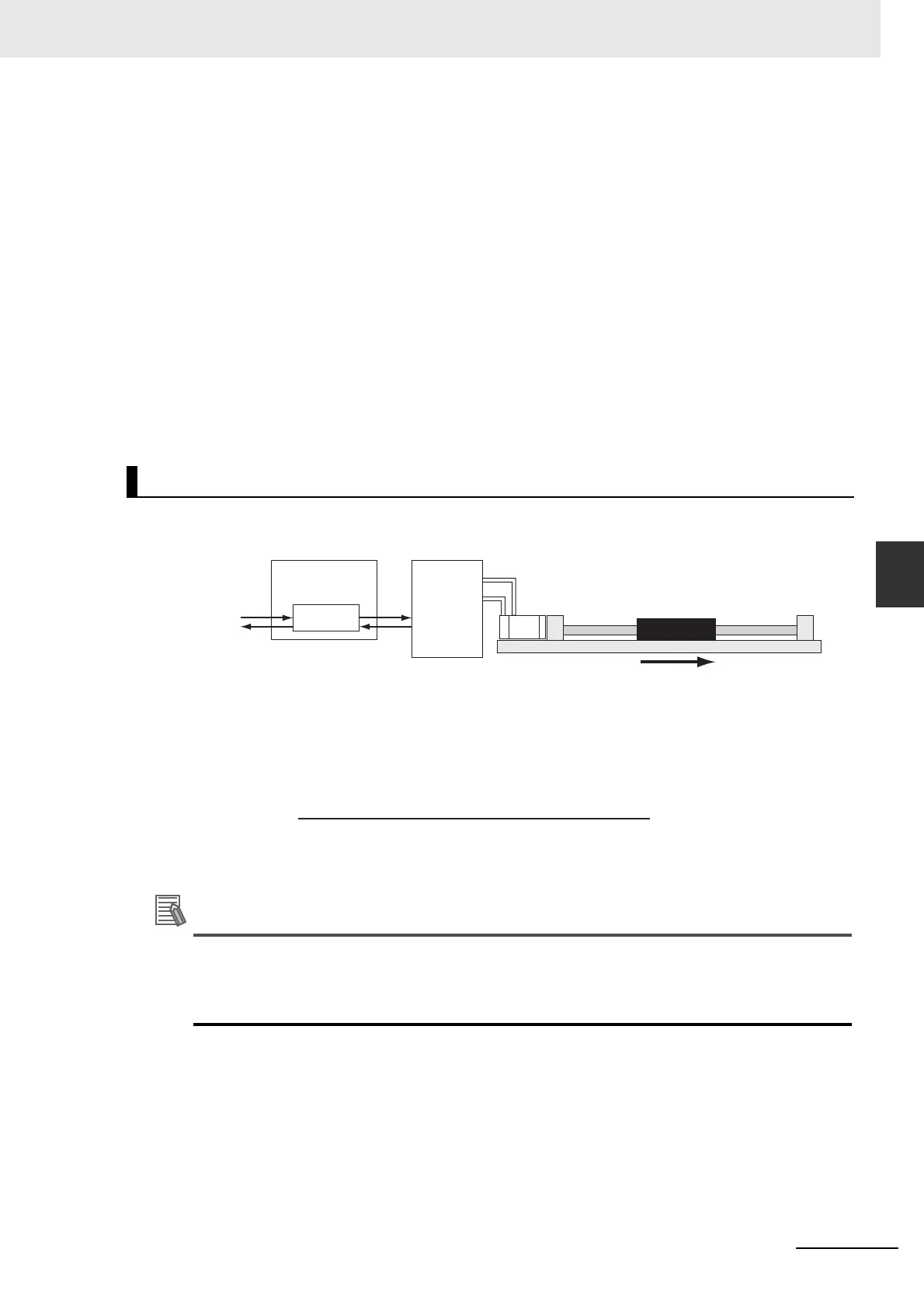
Electronic Gear Ratio (Unit Conversion Formula)
Servo
Drive
X units
Electronic
gear
Command position
(X units)
MC Function
Module
Y pulses
Actual position
(X units)
Work Travel Distance Per Motor Rotation*2 (X Units)
Command Pulse Count Per Motor Rotation*1 (Y Pulses)
Electronic gear ratio =

 Loading...


