EasyManua.ls Logo

Omron NX701-1 User Manual

Omron NX701-1
448 pages
To Next Page IconTo Next Page
To Previous Page IconTo Previous Page
Page #179 background imageLoading...
Page #179 background image
6-27
6 Motion Control Programming
NJ/NX-series CPU Unit Motion Control Users Manual (W507)
6-6 System-defined Variables for Motion Control
6
6-6-3 Tables of System-defined Variables for Motion Control
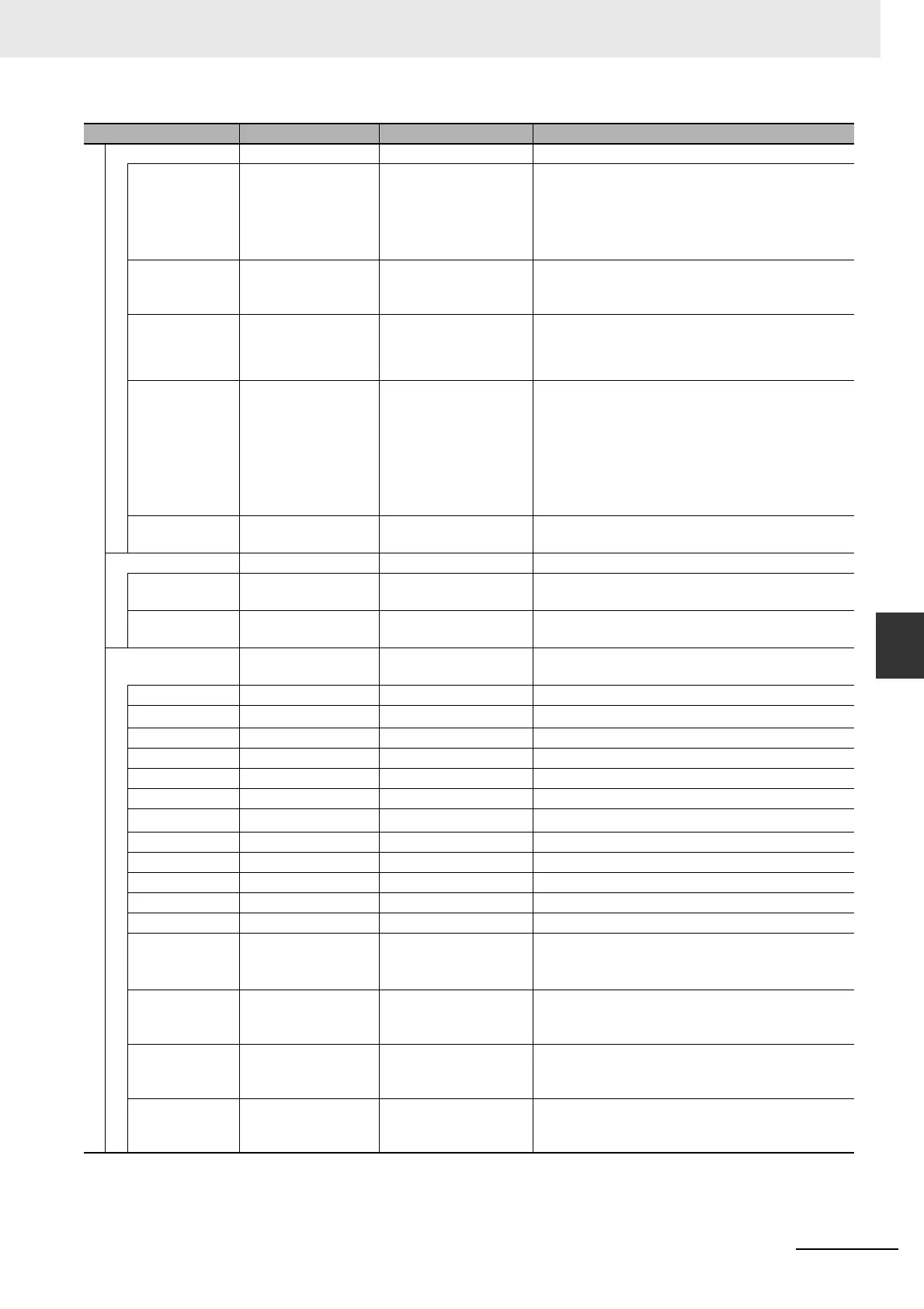
Details _sAXIS_REF_DET Axis Control Status Gives the control status of the command.
Idle BOOL Idle TRUE when processing is not currently performed
for the command value, except when waiting for
in-position state.
*1
Idle and InPosWaiting are mutually exclusive.
They cannot both be TRUE at the same time.
InPosWaiting BOOL In-position Waiting TRUE when waiting for in-position state. The in-
position check performed when positioning for the
in-position check.
Homed BOOL Home Defined
TRUE when home is defined.
*2
FALSE: Home not defined.
TRUE: Home is defined
InHome BOOL In Home Position TRUE when the axis is in the range for home. It
gives an AND of the following conditions.
Home defined
The actual current position is in the zero posi-
tion range with home as the center.
TRUE also when the zero position is passed by
while the axis is moving in command status.
VelLimit
*3
BOOL Command Velocity
Saturation
TRUE while the command velocity is limited to the
maximum velocity during synchronized control.
Dir _sAXIS_REF_DIR Command Direction Gives the command travel direction.
Posi BOOL Positive Direction TRUE when there is a command in the positive
direction.
Nega BOOL Negative Direction TRUE when there is a command in the negative
direction.
DrvStatus _sAX-
IS_REF_STA_DRV
Servo Drive Status Gives the status of the Servo Drive.
ServoOn BOOL Servo ON TRUE when the Servomotor is powered.
Ready BOOL Servo Ready
TRUE when the Servo is ready.
*4
MainPower BOOL Main Power TRUE when the Servo Drive main power is ON.
P_OT BOOL Positive Limit Input TRUE when the positive limit input is enabled.
N_OT BOOL Negative Limit Input TRUE when the negative limit input is enabled.
HomeSw BOOL Home Proximity Input TRUE when the home proximity input is enabled.
Home BOOL Home Input
TRUE when the home input is enabled.
*5*6
ImdStop BOOL Immediate Stop Input TRUE when the immediate stop input is enabled.
Latch1 BOOL External Latch Input 1 TRUE when latch input 1 is enabled.
Latch2 BOOL External Latch Input 2 TRUE when latch input 2 is enabled.
DrvAlarm BOOL Drive Error Input TRUE while there is a Servo Drive error.
DrvWarning BOOL Drive Warning Input TRUE while there is a Servo Drive warning.
ILA BOOL Drive Internal Limiting TRUE when the Servo Drive limiting function actu-
ally limits the axis. This corresponds to one of the
following limits in the G5-series Servo Drive.
*7
CSP BOOL Cyclic Synchronous
Position (CSP)
Control Mode
TRUE when the Servo is ON at the Servo Drive
and the current mode is CSP Mode.
*8
CSV BOOL Cyclic Synchronous
Velocity (CSV)
Control Mode
TRUE when the Servo is ON at the Servo Drive
and the current mode is CSV Mode.
*6
CST BOOL Cyclic Synchronous
Torque (CST)
Control Mode
TRUE when the Servo is ON at the Servo Drive
and the current mode is CST Mode.
*6
Variable name Data type Meaning Function

Table of Contents

Question and Answer IconNeed help?

Do you have a question about the Omron NX701-1 and is the answer not in the manual?

Omron NX701-1 Specifications

General IconGeneral
Ethernet Ports1
USB Ports1
Power Supply24 VDC
I/O PointsUp to 256
Ethernet Port1
USB Port1
SD Memory Card SlotYes
Programming LanguageLadder Diagram, Structured Text, Function Block Diagram
Operating Temperature0 to 55°C

Summary

Introduction

Intended Audience

Information about the target readers of this manual.

Applicable Products

Lists the specific CPU Units covered by this manual.

Relevant Manuals

Manual Structure

Special Information

Precaution on Terminology

Sections in this Manual

Terms and Conditions Agreement

Safety Precautions

Definition of Precautionary Information

Explains the classification of precautionary information within the manual.

Precautions for Safe Use

Precautions for Correct Use

Regulations and Standards

Versions

Checking Versions

Explains how to check unit versions using ID information or Sysmac Studio.

Related Manuals

Revision History

1 Introduction to the Motion Control Function Module

1-1 Features

Describes the capabilities of the Motion Control Function Module.

1-2 System Configuration

Outlines the system components and network configuration for motion control.

1-3 Basic Flow of Operation

Provides a step-by{0}step procedure for performing motion control.

1-4 Specifications

Details the performance and general specifications of the MC Function Module.

2 Motion Control Configuration and Principles

2-1 Internal Configuration of the CPU Unit

Overview of the CPU Unit's software configuration and function modules.

2-2 Motion Control Configuration

Details the configuration of motion control on EtherCAT networks and CPU Units.

2-3 Motion Control Principles

Explains CPU Unit tasks and their relation to motion control execution.

2-4 EtherCAT Communications and Motion Control

Describes EtherCAT communications and their relation to motion control.

3 Configuring Axes and Axes Groups

3-1 Axes

Describes the different types of axes used in motion control systems.

3-2 Axis Setting Procedure

Provides step-by-step instructions for setting up axes in Sysmac Studio.

3-3 Axes Groups

Explains how to group axes for complex operations like linear or circular interpolation.

3-4 Setting Procedures for Axes Groups

Details the procedures for setting up axes groups in Sysmac Studio.

4 Checking Wiring from the Sysmac Studio

4-1 Functions of the Sysmac Studio

Explains how to use the MC Test Run function for wiring checks without programming.

4-2 Monitoring Sensor Signals

Describes how to use the input signal display to check sensor wiring.

4-3 Checking Motor Operation

Details how to check motor operation using functions like Servo ON and Jogging.

5 Motion Control Parameters

5-1 Introduction

Explains axis and axes group parameters for motion control operations.

5-2 Axis Parameters

Details various parameters for configuring axis operations.

5-3 Axes Group Parameters

Explains parameters for setting up axes group operations.

6 Motion Control Programming

6-1 Introduction

Explains programming motion control with EtherCAT slave devices.

6-2 Motion Control Instructions

Provides an overview of motion control instructions based on PLCopen® and MC Function Module specific ones.

6-3 State Transitions

Describes the states of axes and axes groups and their transitions.

6-4 Execution and Status of Motion Control Instructions

Details the rules for executing instructions and their status monitoring.

6-5 Positions

Explains the different types of positions used in motion control programming.

6-6 System-defined Variables for Motion Control

Describes system-defined variables for status and parameter information.

6-7 Cam Tables and Cam Data Variables

Explains the creation and handling of cam tables and cam data variables.

6-8 Programming Motion Controls

Provides procedures for creating programs in Sysmac Studio.

6-9 Creating Cam Tables

Explains how to use the Cam Editor in Sysmac Studio to create cam tables.

7 Manual Operation

7-1 Outline

Describes manual operations using the MC Function Module and OMRON Servo Drives.

7-2 Turning ON the Servo

Details how to turn the Servo ON/OFF using the MC_Power instruction.

7-3 Jogging

Explains how to perform axis jogging using the MC_MoveJog instruction.

8 Homing

8-1 Outline

Describes homing operations when combined with OMRON G5-series Servo Drives.

8-2 Homing Procedure

Provides the steps for setting homing parameters and performing the homing operation.

8-3 Homing Operation

Explains how to select the home definition method based on system configuration and purpose.

8-4 Homing with an Absolute Encoder

Describes how to use absolute encoders for homing and retaining position data.

8-5 High-speed Homing

Explains the function for quick positioning to home using MC_MoveZeroPosition.

9 Motion Control Functions

9-1 Single-axis Position Control

Describes positioning operations for single axes connected to OMRON Servo Drives.

9-2 Single-axis Synchronized Control

Explains synchronized control for single axes using gear or cam operations.

9-3 Single-axis Velocity Control

Details the operation of velocity control for single axes.

9-4 Single-axis Torque Control

Explains how torque control continuously applies a specified amount of torque.

9-5 Common Functions for Single-axis Control

Describes common functions like positions, velocity, and acceleration for single-axis control.

9-6 Multi-axes Coordinated Control

Explains how to set up axes groups for interpolation control of multiple axes.

9-7 Common Functions for Multi-axes Coordinated Control

Details common functions for multi-axes coordinated control, like velocity and acceleration.

9-8 Other Functions

Describes additional functions of the MC Function Module.

10 Sample Programming

10-1 Overview of Sample Programming

Provides information applicable to all sample programming sections.

10-2 Basic Programming Samples

Offers programming samples for MC Function Module's basic functions.

11 Troubleshooting

11-1 Overview of Troubleshooting

Describes methods for checking errors and finding corrections.

Appendices

A-1 Connecting the 1S-series Servo Drive

Describes connections and settings for OMRON 1S-series Servo Drives.

A-2 Connecting the G5-series Servo Drive

Describes connections and settings for OMRON G5-series Servo Drives.

A-3 Connecting to Encoder Input Terminals

Details connections and settings for OMRON GX-series Encoder Input Terminals.

A-4 Connecting to NX Units

Provides information on connecting to NX-series Position Interface Units.

A-5 PDS State Transition

Explains PDS state transitions defined in CiA402 drive profile.

A-6 Terminology

Provides definitions of terms related to motion control.

A-7 Version Information

Details functions added or changed for different CPU Unit and Sysmac Studio versions.

Related product manuals