Appendices
A-8
NJ/NX-series CPU Unit Motion Control User’s Manual (W507)
*1 If required, map the selected process data to a PDO before setting it. The standard setting is 606C hex-00.0
(Velocity actual value).
*2 If you set 6061 hex (Modes of operation display), also set 6060 hex (Modes of operation). Normal operation is
not possible if only one of these two is set.
*3 Map 3010-87 hex (Reference Position for CSP) to a PDO when you use an OMRON 1S-series
Servomoter/Servo Drive.
Precautions for Correct UsePrecautions for Correct Use
• If you change the settings, make sure that the desired operations are performed for the MC
Function Module and process data settings.
• If you are not using an OMRON 1S-series Servo Drive with built-in EtherCAT communications
or G5-series Servo Drive with built-in EtherCAT communications, always set the Modes of
Operation Display (6061 hex).
• To use the MC_SyncMoveVelocity (Cyclic Synchronous Velocity Control) instruction to change
the control mode of an OMRON 1S-series Servo Drive, you need to map Reference Position
for CSP.
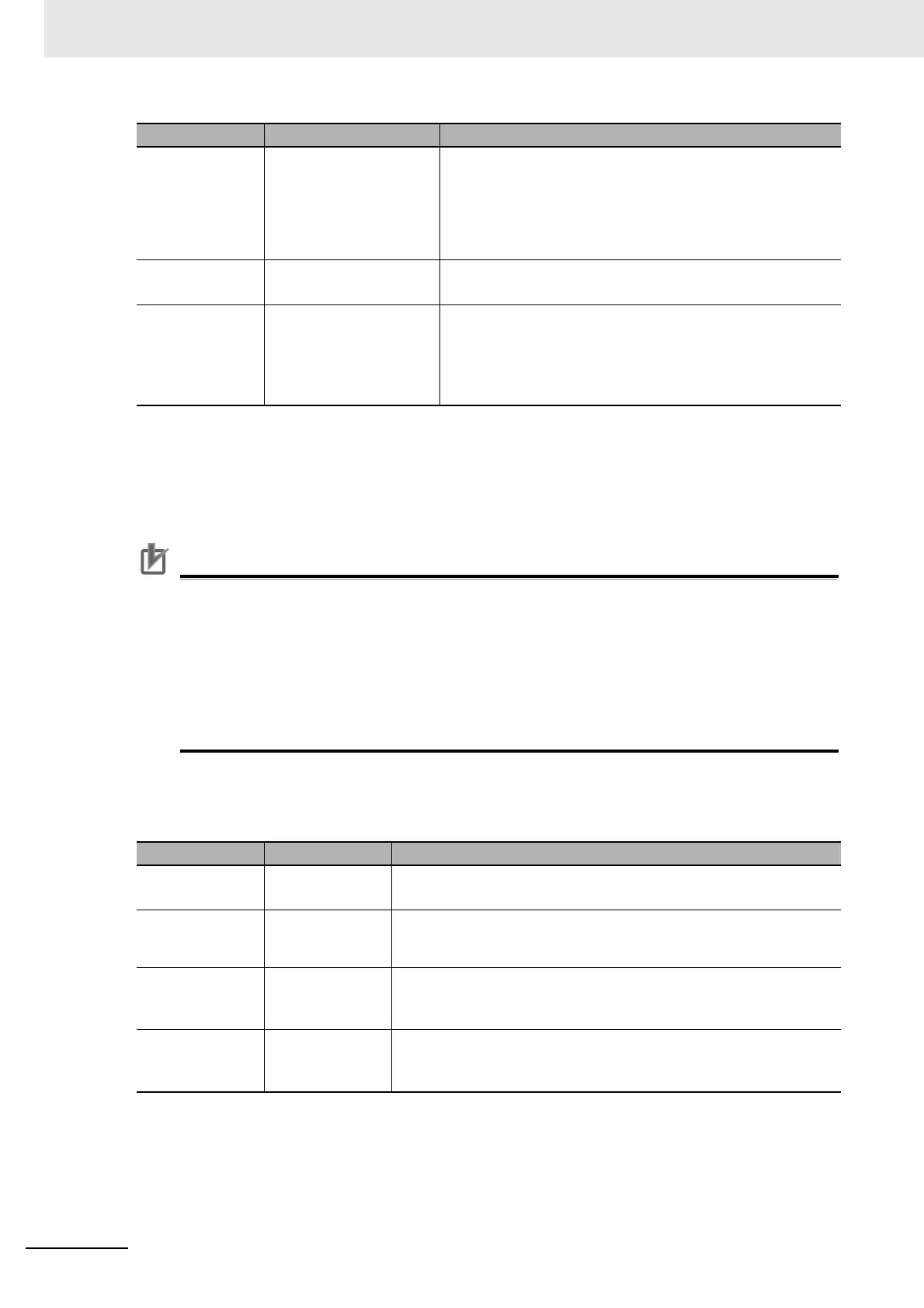
Digital Input Settings
The MC Function Module uses the following input signals of the Servo Drive.
Touch probe
pos2 pos
value
60BC hex-00.0
(Touch probe pos2 pos
value)
The latched position for touch probe 2.
It is required for the touch probe function for the MC_Home,
MC_HomeWithParameter, MC_MoveFeed (Interrupt Feeding),
MC_TouchProbe (Enable External Latch), MC_MoveLink (Syn-
chronous Positioning), and other instructions. Normally set
60BC hex: Touch probe pos2 pos value.
Error code 603F hex-00.0
(Error code)
The error code in the Servo Drive.
Normally set 603F hex: Error code.
Reference
position for
csp
Not set. The reference position for changing the csp mode. This data is
accessed by instructions that are used in Velocity Control
Mode (CSV) or Torque Control Mode (CST).
This object is supported for OMRON 1S-series Servomo-
tors/Servo Drives.
*3
Function name Process data Description
Positive drive
prohibit input
60FD hex-00.1
(Digital inputs)
This signal is used for the positive limit input.
Normally set Bit 1: Positive limit switch of 60FD hex-00: Digital inputs.
Negative
drive prohibit
input
60FD hex-00.0
(Digital inputs)
This signal is used for the negative limit input.
Normally set Bit 0: Negative limit switch of 60FD hex-00: Digital inputs.
Error stop
input
60FD hex-00.25
(Digital inputs)
This signal is used for the immediate stop input.
Set Bit 25: Error stop input of 60FD hex-00: Digital inputs for an
OMRON 1S-series Servo Drive.
Encoder Z-
phase detec-
tion
60FD hex-00.16
(Digital inputs)
Shows the status of detecting the Z-phase input.
Set Bit 16: Encoder phase Z detection of 60FDhex-00: Digital inputs for
an OMRON 1S-series Servomotor/Servo Drive.
Function name Process data Description

 Loading...


