14-11
14 Serial Communications
CP2E CPU Unit Software User’s Manual(W614)
14-3 No-protocol Communications with General Components
14
14-3-2 Flow of Operation
2 The following serial communication ports cannot control RS and ER signals or monitor CS and DR signals.
• ER and DR signals are not supported by the built-in RS-232C port on the E/S-type CPU Unit.
• RS, ER, CS and DR signals are not supported by the built-in RS-485 port of the S-type CPU Unit and
CP1W-CIF11/CIF12-V1 Option Board.
• RS, ER, CS and DR signals are not supported by the RS-232C and RS-485 port of CP2W-CIFD1/CIFD2/
CIFD3 Option Board with two ports.
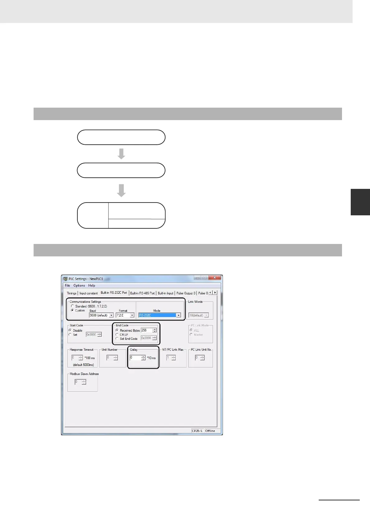
Click the Built-in RS-232C, Built-in RS-485 or Serial Port Tab in the PLC Settings Dialog Box.
14-3-2 Flow of Operation
1
Connect the CP2E CPU Unit and external device using
RS-232C or RS-422A/485 ports.
2
Select Built-in RS-232C, Built-in RS-485 or Serial Port
in the PLC Setup and transfer the PLC Setup from the
CX-Programmer to the CP2E CPU Unit.
(Set the serial communications mode to RS-232C, and
set the communications conditions.)
3
• PLC to External device: Execute the TXD instruction.
• External device to PLC: Execute the RXD instruction.
14-3-3 PLC Setup
Wiring communications
PLC Setup
Create
ladder
Program
Cyclic tasks
Interrupt tasks