8 Overview of Built-in Functions and Allocations
8-6
CP2E CPU Unit Software User’s Manual(W614)
Input terminals are allocated functions by setting parameters in the PLC Setup. Set the PLC Setup so
that each terminal is used for only one function.
z E20/30/40/60, S30/40/60 or N20/30/40/60 CPU Units
Note 1 Only supported by N20/30/40/60 CPU Units.
2 Only supported by N30/40/60 CPU Units.
3 The same pulse inputs must be used for high-speed counter 0 and high-speed counter 1.
4 High-speed counter 2 cannot be used if the input setting of high-speed counter 0 or high-speed counter 1
is set for differential phase inputs (4×), pulse + direction inputs, or up/down pulse inputs.
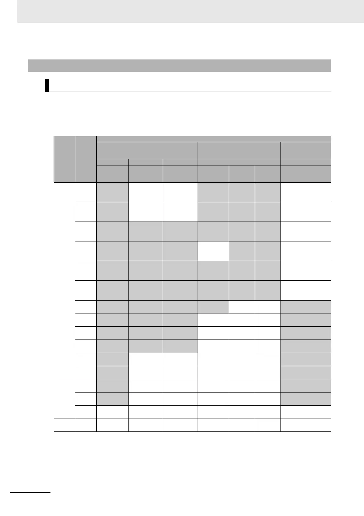
8-3-3 Allocating Built-in Input Terminals
Allocating Functions to Built-in Input Terminals
Terminal
block
label
Terminal
number
PLC Setup
Interrupt input settings on Built-in Input Tab
Page
High-speed counter 0 to 5 settings on
Built-in Input Tab Page
Origin search
settings on Pulse
Output 0 to 3 Tab Page
Normal Interrupt Quick Use Use
Normal input Interrupt inputs
Quick-response
inputs
Increment
pulse input
Differential
phase ×4
or up/down
Pulse/
direction
Origin search
CIO 0
00
Normal input 0
−−
Counter 0,
increment input
Counter 0,
phase A or
up input
Counter 0,
pulse input
−
01
Normal input 1
−−
Counter 1,
increment input
Counter 0,
phase B or
down input
Counter 1,
pulse input
−
02
Normal input 2 Interrupt input 2 Quick-response
input 2
Counter 2,
increment input
Counter 1,
phase A or
up input
Counter 0,
direction
−
03
Normal input 3 Interrupt input 3 Quick-response
input 3
−
Counter 1,
phase B or
down input
Counter 1,
direction
−
04
Normal input 4 Interrupt input 4 Quick-response
input 4
Counter 3,
increment input
Counter 0,
phase Z or
reset input
Counter 0,
reset input
−
05
Normal input 5 Interrupt input 5 Quick-response
input 5
Counter 4,
increment input
Counter 1,
phase Z or
reset input
Counter 1,
reset input
−
06
Normal input 6 Interrupt input 6 Quick-response
input 6
Counter 5,
increment input
−−
Pulse 0, Origin input
signal
07
Normal input 7 Interrupt input 7 Quick-response
input 7
−−−
Pulse 1, Origin input
signal
08
Normal input 8 Interrupt input 8
(Note 1)
Quick-response
input 8 (Note 1)
−−−
Pulse 2, Origin input
signal (Note 2)
09
Normal input 9 Interrupt input 9
(Note 1)
Quick-response
input 9 (Note 1)
−−−
Pulse 3, Origin input
signal (Note 2)
10
Normal input 10
−−−−−
Pulse 0, Origin proximity
input signal
11
Normal input 11
−−−−−
Pulse 1, Origin proximity
input signal
CIO 1
00
Normal input 12
−−−−−
Pulse 2, Origin proximity
input signal (Note 2)
01
Normal input 13
−−−−−
Pulse 3, Origin proximity
input signal (Note 2)
02 to 11 Normal input 14
to 23
−−−−− −
CIO 2 00 to 11 Normal input 24
to 35
−−−−− −