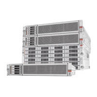
Oracle Database Appliance Version 1 Status Indicators
Callout Indicator/LED: Color State Meaning
immediately following powering on the system. This status
indicates either 1) power-on self-test (POST) diagnostics running
on system host or 2) the host is transitioning from the powered-
on state to the standby state on shutdown.
■ Steady on – The system is powered on and all host POST
tests passed. The system is one of the following states: 1) the
system host is ready to boot, or 2) the system host is booting the
operating system (OS), or 3) the system host is running the OS.
Server Node Internal LEDs
The following section describes the internal LEDs for Oracle Database Appliance Version 1.
Each server node contains the following internal LEDs:
Note - A super capacitor (located on the motherboard) provides power to light the server node
fault LEDs for up to 15 minutes after the server node is removed from a powered-on system
chassis. After approximately 15 minutes, the capacitor discharges enough so that it cannot light
the fault LEDs.
■
Fault Remind Power Good LED.
This green LED lights each time the Fault Remind button is pressed, if the capacitor has
enough of a charge to light the fault LEDs. This LED is located next to the Fault Remind
button.
For the location of Fault Remind button and the Fault Remind Power Good LED, see
“Remove Faulty DIMMs” on page 170.
■
Memory DIMM Fault LEDs
Each DIMM slot has an adjacent DIMM fault LED. If a DIMM fails, the adjacent LED
lights when the Fault Remind button is pressed.
For the location of Fault Remind button and the DIMM fault LEDs, see “Remove Faulty
DIMMs” on page 170.
■
CPU Fault LEDs
Both CPUs have an associated CPU fault LED. If a CPU fails, the associated LED lights
when the Fault Remind button is pressed.
For the location of CPU fault LEDs, see “Remove Processor (CPU)” on page 197.
■
Ethernet Port LEDs
Each server node has two host Ethernet ports (NET0 and NET1) and an SP network
management port (NET MGT). Each of these has two LEDs that indicate link activity and
port speed. See “Ethernet Port Indicators” on page 60.
Chapter 1 • Overview of System Status Indicators and LEDs 59
 Loading...
