SPARE TIRE INSTALLATION
WARNING
Always wear heavy gloves when handling winch cable. Never let cable
run through hands. Frayed cables can cut severely. Failure to comply
may result in serious injury or death to personnel.
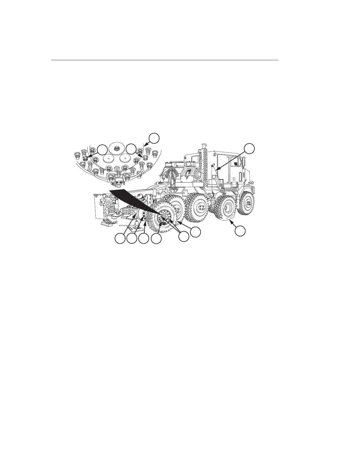
1. With the aid of an assistant, remove cable (1) from spare tire assembly (2).
9
7
4
1
8
3
5
2
6
7
6
Figure 13.
2. With the aid of an assistant, roll spare tire assembly (2) up to axle (3) from which flat
tire assembly (4) was removed.
CAUTION
Position spare tire assembly so that two larger holes in spare tire
assembly are aligned with CTIS fittings. Damage to CTIS fittings and
wheel may result if spare tire assembly is not correctly installed.
NOTE
Spare tire assembly should have CTIS valve facing out.
3. With the aid of an assistant, line up two holes (5) in spare tire assembly (2) with CTIS
fittings (6) in hub (7).
4. With the aid of an assistant, line up 10 holes (8) in spare tire assembly (2) with studs
(9) on hub (7).
TM 9-2320-360-10 0108
0108-16
 Loading...