34
TALLY IP function
Enable TALLY IP to receive OA tally information from the switcher via
the network
The lighting statuses of the camera status indicators on the unit and the
tally lamps on the remote cameras are changed based on the received
OA tally information
Enabling or disabling the TALLY IP function
1 Press the MENU button
2 Open SW FUNCTION menu [42]
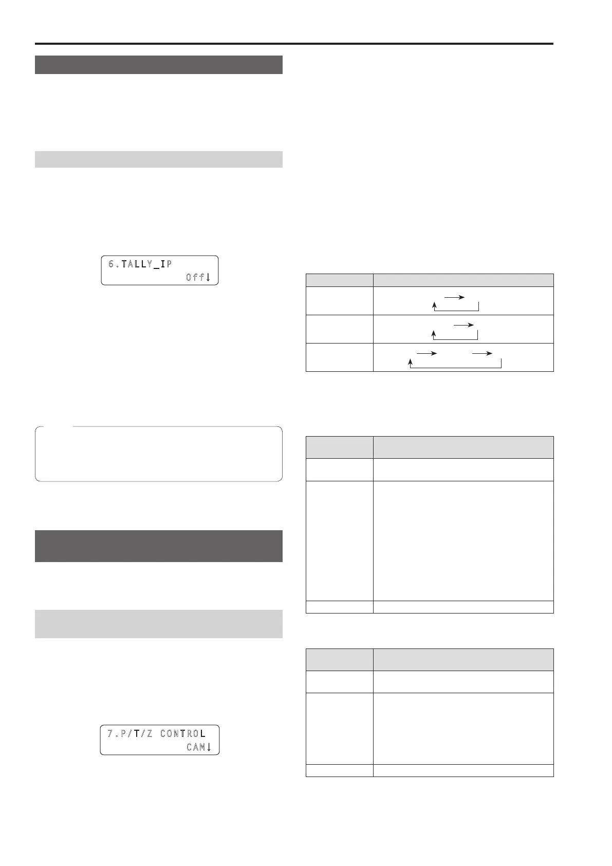
3 Turn the F1 dial to display the “6 TALLY_IP” item
6.TALL Y_IP
Off
4 Turn the F2 dial to select “On” or “Off”, and then press
the F2 dial to confirm the selection
On : Enables the TALLY IP function
Off : Disables the TALLY IP function
To enable tally lamp on instructions to be sent to a remote camera
based on the tally information received from the switcher, you need to
display the “4 TALLY OUT” item in CAMERA SETUP menu [24] and
then set it to “On”
The unit also sends the tally lamp on instruction to the
corresponding remote camera when the unit receives tally
information for a camera number belonging to a camera group
that is not selected
Note
Operating the switcher with the PAN/TILT
lever and ZOOM button
You can use the unit’s PAN/TILT lever and ZOOM button to change
switcher settings (PinP position and size, etc)
Setting the application of the PAN/TILT lever and
ZOOM button
1 Press the MENU button
2 Open SW FUNCTION menu [42]
3 Turn the F1 dial to display the “7 P/T/Z CONTROL” item
7.P/T /Z CONT ROL
CAM
4 Turn the F2 dial to select a setting, and then press the
F2 dial to confirm the selection
CAM:
Allows you to operate the remote camera selected on the unit with
the PAN/TILT lever and ZOOM button
SW:
Allows you to change the switcher settings with the PAN/TILT lever
and ZOOM button
Button Select:
Allows you to select the operation target of the PAN/TILT lever and
ZOOM button (remote cameras or switcher) by pressing the PAN/
TILT ENABLE button or FOCUS/ZOOM/IRIS ENABLE button
For each of the setting values above, the lighting state of the button
indicator changes as follows when the PAN/TILT ENABLE button or
FOCUS/ZOOM/IRIS ENABLE button is pressed
<Change of lighting state when each ENABLE button is pressed>
Setting value Lighting state
CAM
On Off
SW
Blinking Off
Button Select
On Blinking Off
The following shows the operation with respect to the lighting state of
each ENABLE button
<PAN/TILT ENABLE button>
Button indicator
state
Operation when the PAN/TILT lever is operated
On The remote camera is able to move horizontally
and vertically
Blinking
The operation is as follows depending on the state
of the switcher
When Wipe Menu is open
The transition start position (X, Y) can be moved
horizontally and vertically
When PinP Menu is open
The PinP position (X, Y) can be moved
horizontally and vertically
When a chroma key marker is superimposed on
the image output
The chroma key marker position (X, Y) can be
moved horizontally and vertically
Off Operation is disabled
<FOCUS/ZOOM/IRIS ENABLE button>
Button indicator
state
Operation when the ZOOM button is operated
On The lens zoom of the remote camera can be
changed
Blinking
The operation is as follows depending on the state
of the switcher
When PinP Menu is open
The PinP size can be changed
When a chroma key marker is superimposed on
the image output
The chroma key marker size can be changed
Off Operation is disabled
Setting the functions for when the unit is linked with the switcher (continued)

 Loading...