40
Checking alarm information
In the event of an error with the power supply of the unit or a remote
camera included in the selected camera group, the ALARM indicator on
the unit turns on and the output of the GPI OUT connector (GPI OUT 5)
becomes On
When an error occurs, you can check the alarm information by menu
operation
Displaying alarm information
1 Press the MENU button
2 Open ALARM menu [50]
3 Turn the F1 dial to display the item you want to check
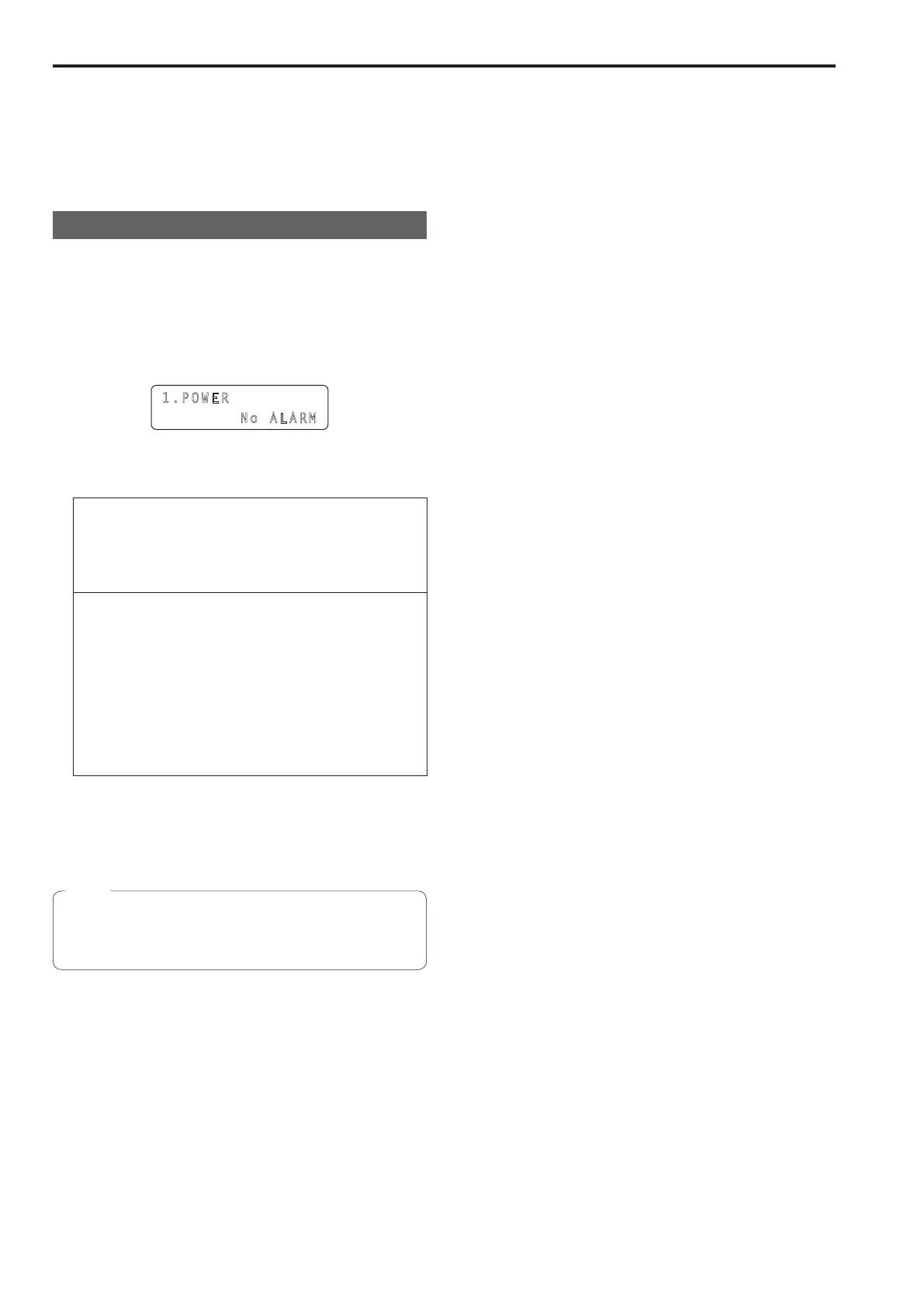
The alarm status is displayed on the bottom line of the LCD panel
1.POWE R
No ALARM
<Details of each alarm>
[Select 1 POWER]
Allows you to check the unit’s power supply alarm
No ALARM:
When the power supply is trouble‑free
ALARM:
When trouble has occurred with the power supply
[Select 2 CAM### to 11 CAM###]
(
*
1)
Displays the alarm information for camera numbers included in the
currently selected camera group
No ALARM:
Trouble‑free
FAN ALM:
Trouble has occurred with the cooling fan
P/T ALM:
Trouble has occurred with the pan/tilt operation
FAN ALM+P/T ALM:
Trouble has occurred with the cooling fan and pan/tilt
operation
(
*
1) CAM### is used to indicate a camera number included in the
selected camera group For example, when the F1 dial is turned
while camera group “10” is selected, “2 CAM91” to “11 CAM100”
are displayed on the top line of the LCD panel
When an alarm has occurred, stop operation immediately and be
sure to contact your dealer
Continued use may cause the unit or a remote camera to
malfunction
Note
 Loading...