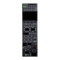
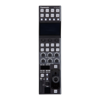
44
Registering camera numbers to CAM OUT1 to
CAM OUT10
1 Press the MENU button
2 Open GPI OUT menu [45]
3 Turn the F1 dial to display the “1 CAM OUT1” item
1.CAM OUT1
C AM1
4 Turn the F2 dial to select the camera number to set for
CAM OUT1, and then press the F2 dial to confirm the
selection
Camera number : Select from CAM1 to CAM100
5 Turn the F1 dial to display any of the “2 CAM OUT2”
to “10 CAM OUT10” items and then register a camera
number
Repeat steps 3 to 4
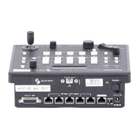
REMOTE
(JST: JEY‑9P‑1A3F(LF)(SN))
You can connect a personal computer or other external device to select
the camera group, select the remote camera, and recall preset memory
or tracing memory
For further details, contact your dealer
1 5
6
9
Pin number Signal name
1 ‑‑‑
2 RXD IN
3 TXD OUT
4 DTR
5 GND
6 DSR
7 RTS
8 CTS
9 ‑‑‑
TO PAN/TILT HEAD 1 to 5 connectors
(RJ‑45)
Connect remote cameras with support for a serial connection to these
connectors using LAN cables
Connect them with straight cables (category 5 or better shielded cable)
Pin
number
Signal name Description of signal
1 GND Frame ground
2 TALLY Tally output (open collector)
3 TXD – Send data (–)
4 RXD – Receive data (–)
5 RXD+ Receive data (+)
6 TXD+ Send data (+)
7 NC Not used
8 NC Not used
TALLY (pin number: 2) specifications
Voltage withstand: Max 24 V DC
Current: Max 50 mA
LAN connector (RJ‑45)
Connect a remote camera, switcher, or computer that supports an IP
connection to this connector with a LAN cable
When directly connecting a device to the unit, use a crossover cable
(category 5 or better shielded cable)
When connecting via a hub (switching hub) or other device, use a
straight cable (category 5 or better shielded cable)
Control interface for external devices (continued)
 Loading...