AT Commands/Registers/Modem Messages
FP Modem-EU Technical Manual
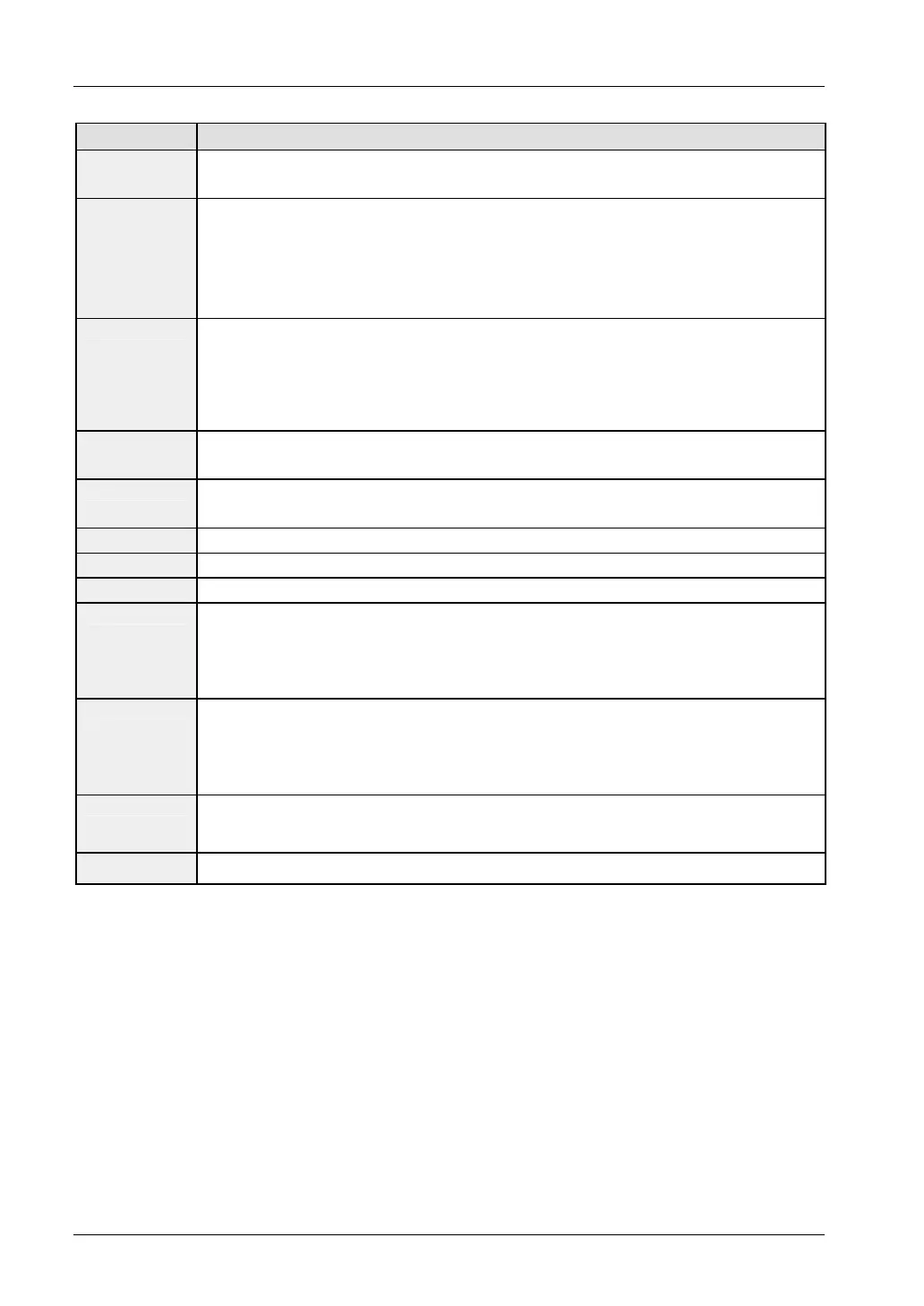
Command Description
&Fn
n=0 or only AT&F: recall factory setting 0
n=1 recall factory setting 1
&Kn
Note: This command replaced AT\Q !
n=0 DTE/DCE flow control switched off
n=3 switch on RTS/CTS DTE/DCE flow control
n=4 switch on XON/XOFF DTE/DCE flow control
n=5 switch on unidirectional XON/XOFF flow control
&Nn
Terminating resistor for multipoint operation (see "Multipoint Operation" on page 61), entry in
register S91
n=0 terminating resistor only when sending
n=1 terminating resistor always off
n=2 terminating resistor always on
&Rn
n=0 CTS follows after RTS (as in V.24 specification)
n=1 CTS always active
&Sn
n=0 handshake signal DSR always active
n=1 DSR deactivated if flow control is required (as in V.24 specification)
&V
Display current configuration and stored profiles 0 and 1
&Wn
Save current configuration in user profile (0 to 1)
&Yn
Recall user profile n (0 or 1) upon next power up
&Zn=x
Store dial string x (up to 30 digits) to location n (0 to 20)
Telephone number
0 is decisive for the password and call-back function (also see below: AT\F)
Telephone number
1+2 is also used by the CLIP function (only V1.2)
Telephone number
20 is decisive for the ASCII fax function
\An
n=0 set max. block size in MNP to 64
n=1 set max. block size in MNP to 128
n=2 set max. block size in MNP to 192
n=3 set max. block size in MNP to 256
\Bn
Sends a break signal to the calling modem that terminates the connection. n* 100ms
(factory setting n=3; see below: AT\Kn and also (see "
Disconnection with the Break Signal" on
page 50))
\F
Reports a list of all stored telephone numbers (stored with AT&Z)
70

 Loading...


