■
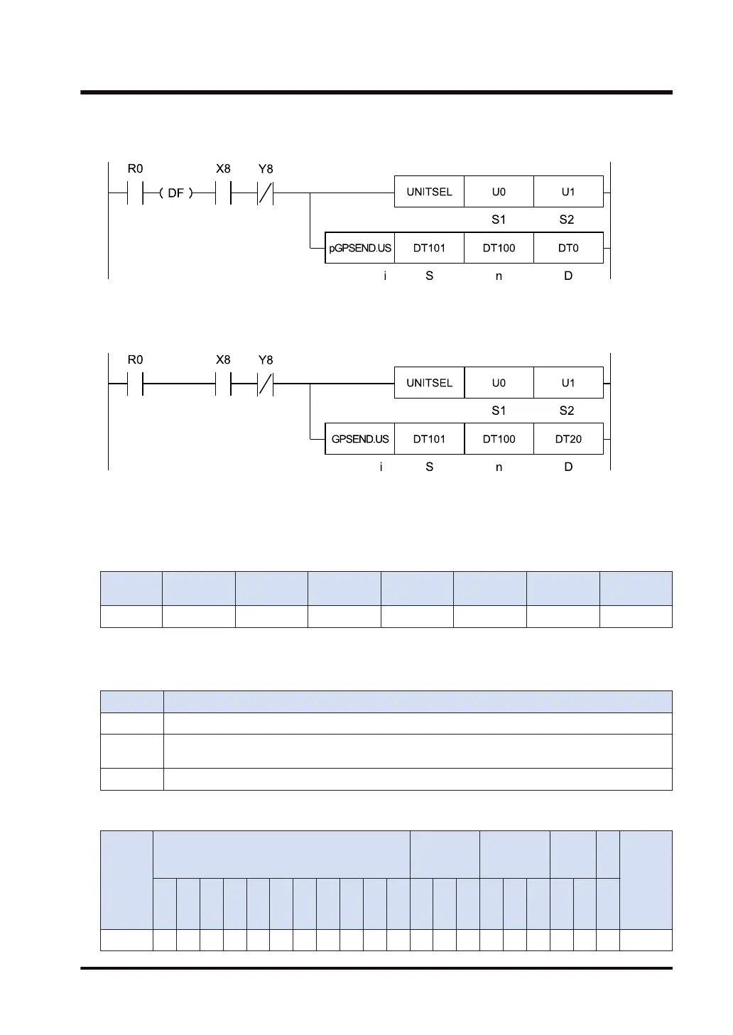
Ladder diagram (pGPSEND)
■
Ladder diagram (GPSEND)
(Note 1) The above figure shows the case that S1=U0 (CPU unit with built-in SCU) and S2=U1 (port number 1)
are specified by the UNITSEL instruction.
■
Available operation units (●: Available)
Operatio
n unit
bit US SS UL SL SF DF
i ● ●
(Note 1) When a negative value is specified for operand [n], it is necessary to specify an SS operation unit.
■
List of operands
Operand Description
S Starting number for the device for storing the sent data
n
Number of bytes of the sent data, or starting number of the device where the amount of sent data is
stored
D Starting number of the device that stores the processing result (1 word)
■
Available devices (●: Available)
Operan
d
16-Bit device:
32-Bit
device:
Integer
Real
numbe
r
St
rin
g
Index
modifie
r
W
X
W
Y
W
R
W
L
W
S
S
D
D
T
L
D
U
M
WI
W
O
TS
C
S
TE
C
E
IX K U H SF
D
F
" "
S1 ● ● ● ● ● ● ●
9.3 Sending Operation
WUME-FP7COM-07 9-7

 Loading...


