Page 9
Ph: 804.227.3023
10511 Old Ridge Rd. Ashland, VA 23005
v 2.0
Powertrain Control Solutions
4.2.4 On-Board I/O
The On-Board I/O button from the Main Menu is a very useful screen when testing and debugging a new installation.
This screen displays all the raw voltages from each analog input, plus its abbreviation as assigned in the software, and
its defi ned function. It also displays the raw input on the speed channel. If this number is 0, then the speed input is not
registering an input. If the number is non-zero, it will not display frequency and it may be more useful to view the data from
a Monitor Screen. The two PWM output duty cycles can be viewed as well.
4.2.4.1 PWM Output Override
To test the PWM outputs, select PWM Control. Select either PWM1 or PWM2. When the output is under dash control, its
current duty cycle will be displayed in the box in the center of the screen. When the output is under User Control, it will
output the duty cycle the user has entered in the box. To enter a duty cycle, touch the box and use the keypad to enter a
number.
4.2.5 Advanced
The Advanced Menu provides access to any advanced feature menus, current unlock status of a feature, and access
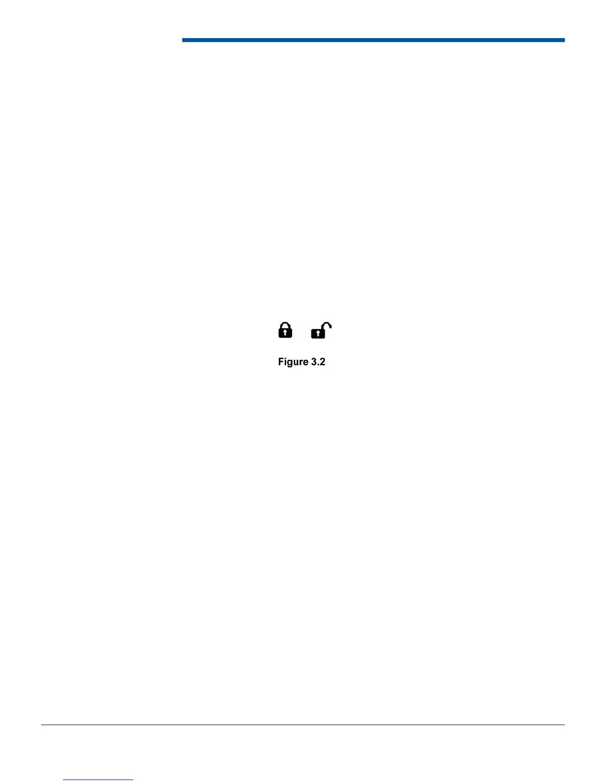
to the feature activation screen. Selecting All Features from the Advanced Features Menu will show the status of all the
advanced features. A locked padlock as shown in Figure 3.2 indicates the feature is not enabled. To activate it, press the
Activate button and follow the instructions in Section 4.2.5.1. An unlocked padlock as shown in Figure 3.2 and the word
Unlocked next to the feature indicates the feature has been activated.
4.2.5.1 Advanced Feature Activation
To activate an advanced feature, a 12-digit activation code is required. This code can be purchased by contacting PCS
and supplying your D200’s serial number. If the feature was purchased at the time of order an activation code was
included with the D200. To activate the feature, go to the Main Menu then select Advanced then All Features. Press the
activate button for the feature requiring activation. Enter the12-digit activation code using the keypad and then press
Enter. The feature should activate and the locked symbol should change to unlocked. If the activation key was incorrectly
entered, select the Activate button again to retry it. After three failed attempts, the D200 will need to be reset to try again.
The activation code is keyed specifi cally to the feature and a serial number in each D200.
4.2.6 Monitor Settings
The Monitor Settings menu is used to select display data and units. Display data is used to select the individual data items
from a particular device to display. The Units Menu allows the selection of units as well as tachometer and speedometer
settings for communication inputs.
4.2.6.1 Set Display Data
The Set Display Data Menu is used to select the particular items from the sources that you wish to monitor. For example,
if a transmission controller is communicating with the dash, you may want to monitor vehicle speed but do not want
to monitor accumulator pressure. Therefore, you can enable vehicle speed and disable accumulator pressure. In this
example, if you went to the monitor screen you would see (or have the option to see by selecting a gauge to change)
vehicle speed from the transmission controller.
The Set Display Data Menu is populated with buttons for every communication device that is enabled. The On-Board
Inputs button is always on this screen and includes inputs, outputs, and other dash data such as internal temperature,
battery voltage, current gear, and real-time clock time. Select a device to change its displayed data. If the device has
more than one page of data, the More button will appear to go to the next page. The Clear Page button clears the data
selected for that page. The counter at the bottom of the screen counts all of the inputs selected. The displayed data
setting for a device does not change the logging parameters. For example, if a parameter such as RPM is disabled from
displayed data, it will still be logged at its devices rate.