PCS D200 Dash Logger User Guide
Page 30
Ph: 804.227.3023
10511 Old Ridge Rd. Ashland, VA 23005
v 2.0
The dash has 16 programmable alarms to monitor input channels and alert the driver if an input is out of range. The alarm
setup form is under the Basic Features option in the tree-view or the menu bar. Double click it to open the form. The fi rst
column is the source device that will trigger the alarm. The Second column is the channel of the selected device that
requires monitoring. The third column or Low Alarm is the value below which the alarm condition exists. For example, this
could be used for Oil Pressure less than 20 PSI. If the channel does not have a low alarm value, then enter a very small
number or zero, such that the channel can not get into the low alarm state. The next column is the High Alarm value.
This is the value above which is considered an alarm state. When the channel value exceeds the value in the High Alarm
column, it will trigger the alarm. Similar to the Low Alarm, if the particular channel does not have a High Alarm, enter a
very high value that it can never reach.
When an input is out of range, there are two ways it can indicate to the driver that there is a problem. The default way is
to fl ash the item on the screen until the input is back within the limits. This will only alert the driver if that particular item is
selected for view on that monitor screen. If the item is not viewable then the driver will not be able to see any indication of
a problem. However, the alarms also have the capability to be linked to a PWM output channel providing an output such
as a warning light when a certain condition exists. Each alarm channel can be linked to either PWM output channel 1 or 2
by selecting the checkbox for that alarm. The PWM must be set up as an Alarm Function as described in Section 6.7.4.
The output will turn on if any of the linked alarms reach an alarm condition.
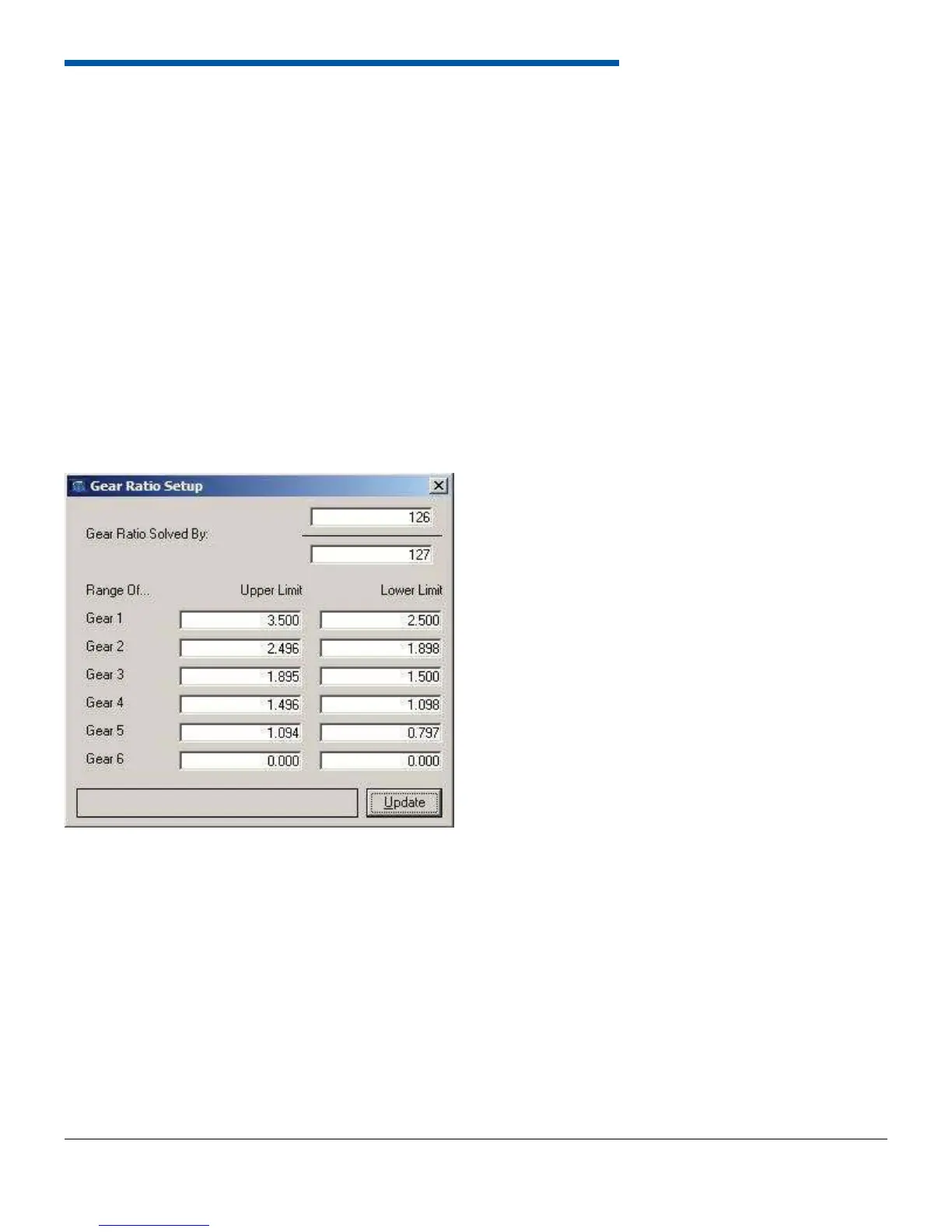
6.8.2 Gear Ratio Setup
The dash can calculate gear ratio given an input shaft speed and a drive shaft speed measurement. The two speed
measurements are typically run to the on-board speed inputs. To determine gear ratio, the dash must divide one speed
by the other. The top half of the window allows assignment of the numerator and denominator in the gear ratio calculation.
Then enter the gear ratio range for each gear. If the dash detects zero speed, it will return to gear 1. If the dash detects a
gear ratio not defi ned in the calibration, it will remain in the last calculated gear. The dash current gear can be monitored
using the CGER label from the On-Board Inputs and is data logged with the dash Data.