PCS D200 Dash Logger User Guide
Page 4
Ph: 804.227.3023
10511 Old Ridge Rd. Ashland, VA 23005
v 2.0
2.2.1 Power and Ground
The D200 Dash Logger requires a fused, switched, power connection from 9VDC to 18VDC. The dash draws approximately
0.4 amps without the PWM outputs turned on. If the PWM outputs are used to drive a device such as a shift light, the
power requirements for the dash will increase accordingly. The dash harness is equipped with a 10-amp inline fuse and
switched power should be connected to the red wire coming from the fuse holder. Ground should be connected to the
black wire coming out of the harness with the fused power wire.
2.2.2 On-Board Inputs
The D200 Dash Logger has 8 analog inputs and 2 speed inputs. The analog inputs can be connected to any 0-5V sensor.
If a sensor requires a 5V reference voltage, use pin 26, red/white, for a regulated +5V DC source. For a sensor ground
source, use pin 27, black/white. Analog inputs 7 and 8, pins 24 and 25 respectively, have programmable 1000-ohm pull-
up resistors in the dash. These are typically used with a temperature sensor but must be disabled for use with a typical
5V sensor. This pull-up may be enabled in the software.
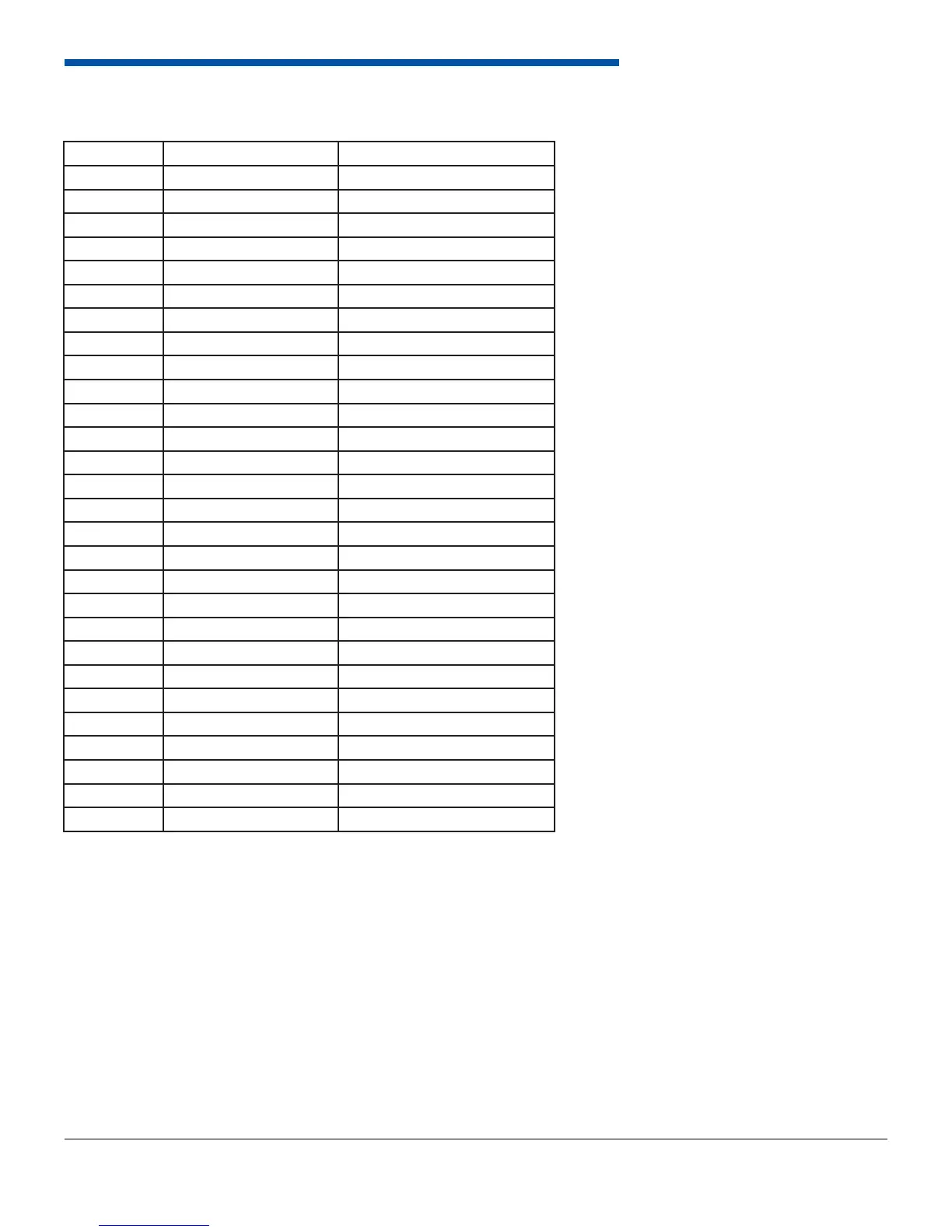
2.2 Wiring
Pin # Wire Color Function
1 Red Power (Switched +12 VDC)
2 Not Used Reserved
3 Not Used Reserved
4 Not Used Reserved
5 Not Used Reserved
6 Not Used Reserved
7 Violet/Black PWM 1
8 Violet/Red PWM 2
9 White/Red CAN A High
10 Not Wired CAN B High
11 Not Wired CAN B Low
12 Brown/Black RS-232 Transmit
13 Brown/Red RS-232 Receive
14 Brown/Blue RS-232 Ground
15 White/Black CAN A Low
16 Orange/Black Speed Input 1
17 Orange/Red Speed Input 2
18 Gray/Black Analog Input 1
19 Gray/Red Analog Input 2
20 Gray/Light Green Analog Input 3
21 Gray/Light Blue Analog Input 4
22 Gray/White Analog Input 5
23 Gray/Orange Analog Input 6
24 Gray/Yellow Analog Input 7
25 Gray/Pink Analog Input 8
26 Red/White Reference 5V Output
27 Black/White Sensor Ground
28 Black Ground