PCS D200 Dash Logger User Guide
Page 16
Ph: 804.227.3023
10511 Old Ridge Rd. Ashland, VA 23005
v 2.0
The On-Board Inputs section provides access to the calibration for the eight analog inputs and the two speed inputs. From
the tree-view, double-click on the word On-Board Inputs, to show Analog Inputs 1 through 8 and Speed Inputs folders.
Double-click on the Analog Input you want to edit.
6.4 Analog Inputs
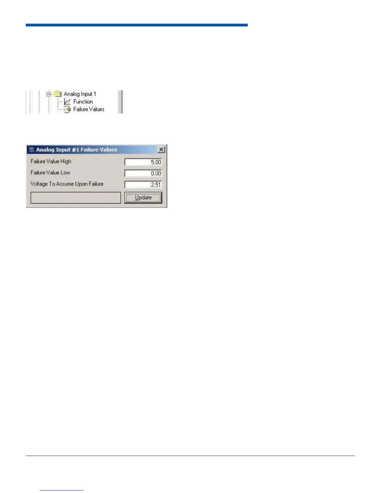
Each Analog Input contains two forms to edit in the software; Function, and Failure Values.
The failure values for a channel set the maximum and minimum for that channel. These values are 0-5V and are
independent from the input function. If the input voltage exceeds the Failure Value High value, it will disregard the high
input voltage and use the Voltage to Assume Upon Failure voltage. Likewise, if the input voltage is below Failure Value
Low, it will use the Voltage to Assume Upon Failure voltage. The channel will then use the channel function (if defi ned) to
translate the voltage to a converted value (i.e. Boost, or Air Temp).
The function form allows the user to select the function the channel will perform. Setting the function assigns an identity
to the channel which includes units, labels, gauge type, and the calibration to relate voltage from the sensor to a human
readable value such as Pressure. The available functions for the analog inputs are listed below.
• Voltage
• Percentage
• Data Log Enable
• Lambda
• Night Mode
• Position
• Pressure
• Temperature
• Disable Touchscreen
• Timing Beacon
Each analog input channel can be assigned an input description and a displayed label. The input description is a
20-character name assigned to the channel that will be displayed in the data logs. The displayed label is a 4-character
word or acronym that will be displayed throughout the dash to reference that channel.
Analog inputs 1 through 6 do not have programmable pull-up resistors. Analog inputs 7 and 8 do have programmable
1000-ohm pull-up resistors. To enable the resistor open the analog function form for that channel and select the checkbox
labeled Enable Pull Up Resistor. The pull up resistor is used for temperature sensors and any 2 wire sensor whose
reading is based on resistance. When channels 1 through 6 are disconnected from anything they will read 0V. When
channels 7 or 8 are disconnected, they will read approximately 4.38 volts with the pull-up disconnected, and 4.91 volts
with the pull-up enabled.