Page 5
Ph: 804.227.3023
10511 Old Ridge Rd. Ashland, VA 23005
v 2.0
Powertrain Control Solutions
The speed inputs, pins 16 and 17, can be connected to a magnetic or hall-effect sensor. The speed inputs have
programmable 1000-ohm pull-up and pull-down resistors in the dash to accommodate a wide range of sensors.
2.2.3 On-Board Outputs
The D200 Dash Logger has 2 PWM outputs. These are high side (+12V) outputs capable of driving a constant current
of 6-amps each or a peak current of 30- amps. The power connection must be able to source the required power for the
outputs.
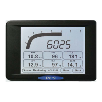
The D200 Dash Logger has one RS-232 serial connection typically used for connecting to an aftermarket engine controller
or GPS receiver. The RS-232 connection is on the back 28-pin circular connector and comes out of the harness on a 9-pin
circular connector. For connecting to a device with the normal 9-pin DB9 connector, the purchase of the ECU connection
kit is required. The 9-pin DB9 connector on the side of the dash is only used for pass-through communication and can not
be used to connect an RS-232 device to the dash.
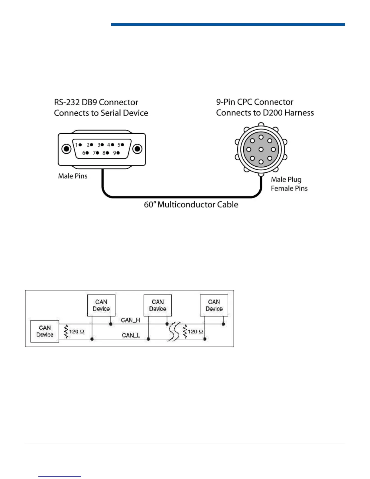
2.2.5 Controller Area Network (CAN)
The D200 Dash Logger has two CAN interfaces, CAN A and CAN B. Both receive CAN information, but only CAN A
can be used to tune the PCS Transmission Controller. CAN A is a two wire (White/Red and White/Black) twisted pair
connected to a 2-pin Deutsch connector on the dash harness. For CAN communication, both wires must be connected
to the device and a terminating resistor must be at each ends of the harness. Multiple devices can be connected on the
same CAN network if the devices communicate at the same speed.