Connectors
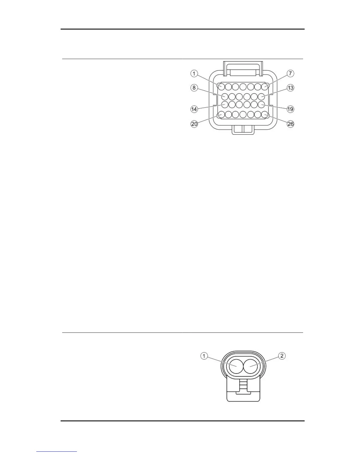
INJECTION ELECTRONIC CONTROL UNIT
1. Injection telltale light (Brown-Black)
2. Rpm indicator on instrument panel (Yellow)
3. CAN "L" Line (White-Blue)
4. Lambda probe (-) (White-Green)
5. Live supply (Red-White)
6. Battery powered (Orange-Black)
7. Immobilizer aerial (Orange-White)
8. Electric fan remote control (Blue-Yellow)
9. Coolant temperature sensor (Sky blue-Green)
10. CAN "H" Line (Pink-White)
11. Lambda probe (+) (Sky blue-Black)
12. Engine stop switch (Green-Black)
13. Engine revolution sensor positive (Red)
14. Fuel injector (Red-Yellow)
15. Engine revolution sensor negative (Brown)
16. Diagnosis (Purple-White)
17. Immobilizer LED (Red-Green)
18. Engine stop switch, coolant temperature sen-
sor (Grey-Green)
19. Not connected
20. Injection load remote control (Black-Purple)
21. Not connected
22. HV coil (Pink-Black)
23. Not connected
24. Start-up enabling switch (Orange-Blue)
25. Not connected
26. Ground (Black)
PICK-UP CONNECTOR
1. Injection electronic control unit (Red)
2. Injection electronic control unit (Brown)
MP3 400 i.e. Electrical system
ELE SYS - 29