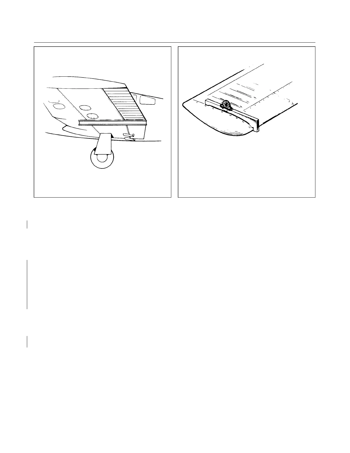
Figure 5-4. Aileron Rigging Tool Figure 5-5. Stabilator Rigging Tool
5. Tighten the bolts to secure the idler cross-over sprockets.
6. Remove any rigging locks or tools previously installed.
d. Check the ailerons for correct travel from neutral per dimensions given in Table V-l, by the following
procedure:
1. Center the bubble of a protractor over the surface of an aileron at neutral position and note the
reading.
2. Move the aileron full up and down, and check the degree of travel for each direction. When
measuring the full down position of the aileron, maintain a light up pressure at the center of the
trailing edge of the aileron. When measuring the full up position of the aileron, maintain a light
down pressure at the center of the trailing edge of the aileron. This pressure should be just
s u fficient to remove the slack between the bellcrank and aileron. The degree of travel on the
protractor is determined by taking the difference between the protractor reading at neutral and up,
and neutral and down. The bubble must be centered at each reading.
3. Should the travel not be correct, the travel may be set by rotating the bellcrank stops in or out.
Stops are located in the wing attached to the rib that is adjacent to the aileron bellcrank.
4. Repeat this procedure for the other aileron.
e. Check to insure that the left aileron up and right aileron down stops are contacted simultaneously and
vice versa. Adjust stops as required.
f. Check the bellcrank stops to assure that the bellcrank contact is made simultaneously, but still have
cushion before contacting the control wheel stops. Maintain .030 to .040 clearance between sprocket
pin and adjustable stop bolts on the tee bar.
NOTE
When an out of trim condition persists despite all the rigging corrections
that can be made, there is a possibility that the trailing edge of the aileron
has been used to move the aircraft forward. This can result in a slight
bulging of the aileron contour at the trailing edge which will cause an out
of rig condition that is very difficult to correct.
Revised: 5/1/80
1F20
* CHEROKEE ARROW III SERVICE MANUAL
SURFACE CONTROLS