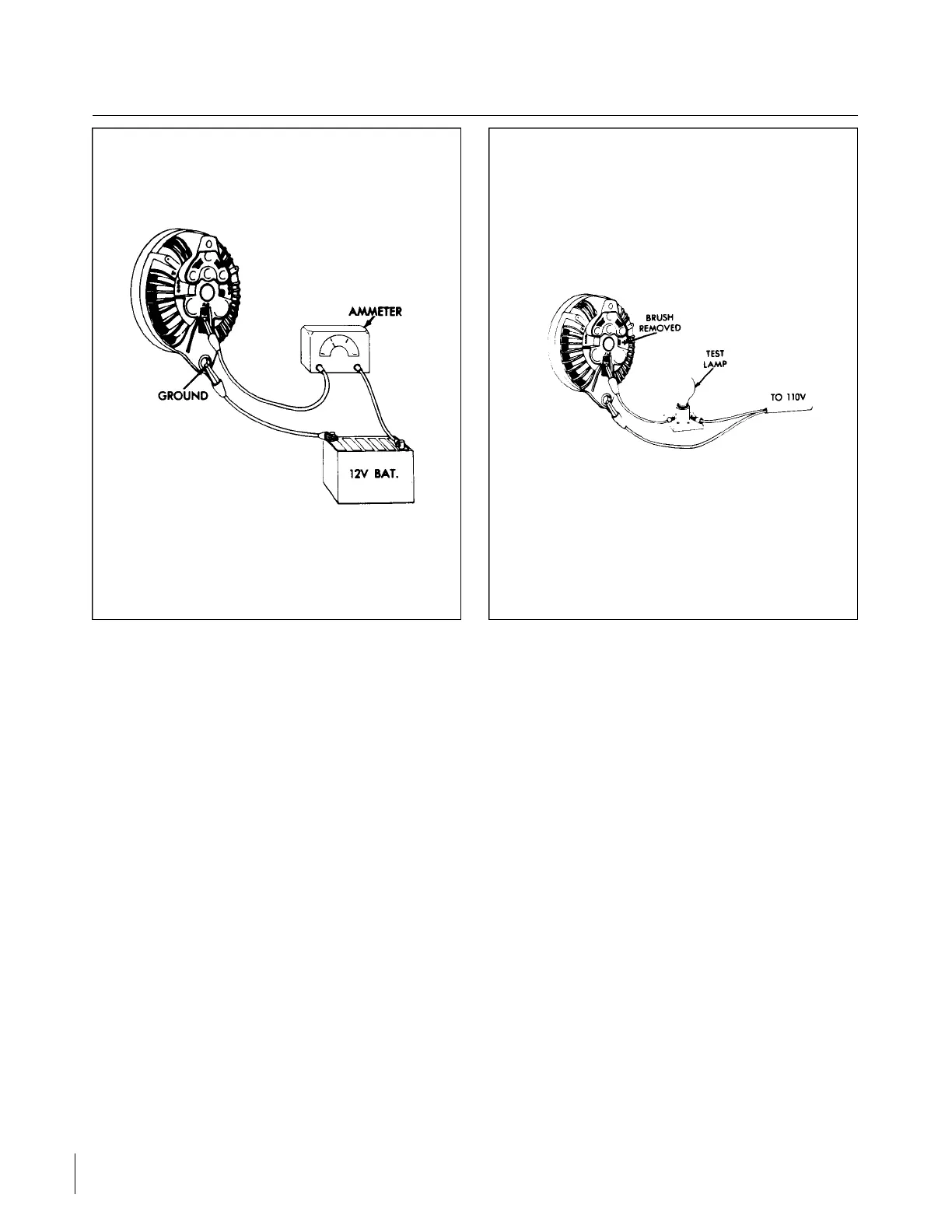
Figure 11-3. Checking Field Circuit Figure 11-4. Testing Field Circuit
11-9. TESTING ALT E R N ATOR INTERNAL FIELD CIRCUIT FOR A GROUND. To test the alternator
internal field circuit for a short circuit foreground, proceed as follows:
a. Remove the ground brush and using a 110-volt test lamp, place one test probe to the field terminal and
the remaining test probe to a machined surface at one of the alternator end shields. (Refer to Figure 11 - 4 . )
The test land should not light.
If the test lamp lights, carefully observe the order in which the parts were installed as you remove the
insulated brush assembly. Remove the three through bolts. Then, separate the two end shield assemblies.
Touch one of the test lamp probes to one of the slip rings and the remaining test probe to the rotor shaft. The
lamp should not light. If the lamp lights, the rotor assembly is grounded and requires replacement.
If the test lamp does not light, the ground condition was in the insulated brush assembly and the parts were
either assembled wrong or damaged and short circuiting through to ground. Inspect the brush holder and
insulated washer. Replace if damaged. The stack of parts attaching the insulated brush holder assembly to the
end shield must always be installed in the proper sequence as follows: Insulated brush holder, “FLD” terminal,
insulating washer, lockwasher and attaching screw.
11-10. INSPECTION. Inspect the condition of the alternator components paying special attention to the
condition of the slip rings for indications of oil, being burnt or worn. Inspect brushes for signs of sticking in
holder or shield and for wear.
Inspect the bearing surface of the rotor shaft and the roller bearings at the rectifier end. Rotate the rotor in
the drive end shield to feel roughness in the drive end bearing. Inspect the grease retainer. Inspect the rectifier
leads especially at connections for a good solder joint, also inspect insulation. Rectifier/stator lead must be
pushed down into the slots that are cast into the end shield and cemented with MoPar Cement #2299314.
Revised: 2/13/89
2G21
CHEROKEE ARROW III SERVICE MANUAL
ELECTRICAL SYSTEM