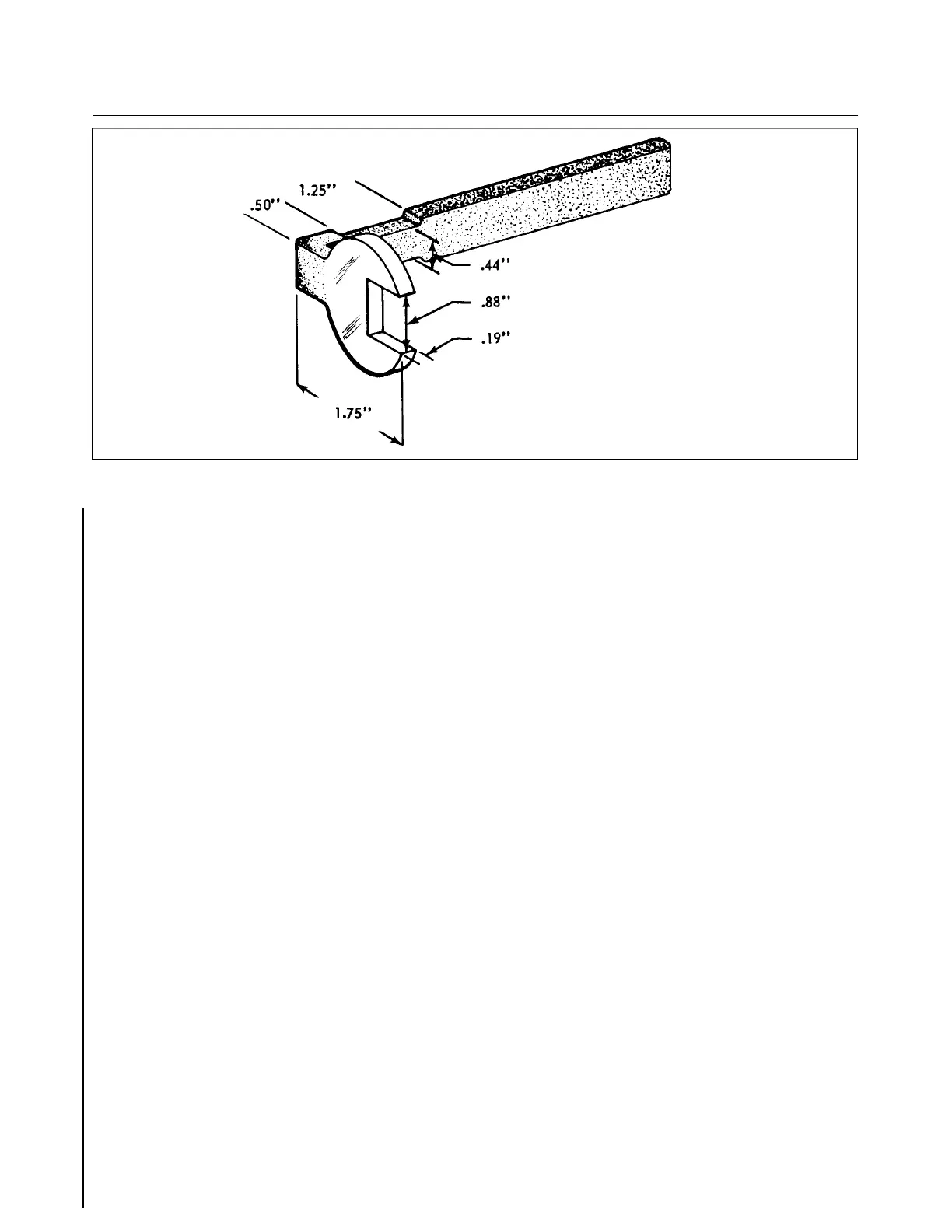
Figure 4-8. Fabricated Tool for Baggage Door Lock
4-55a. BAGGAGE COMPARTMENT INSPECTION HOLE AND COVER PLATE.
(See latest revision of Piper Service Bulletin 977.)
a. General.
Airplanes manufactured before 1979 may not have had control cable inspection access holes in the
baggage compartment floor. The following is a method of fabricating inspection access holes in the floor of
the baggage compartment, if desired.
b . Baggage Compartment Inspection Holes Fabrication Procedure. (Refer to Figure 4-8a.)
While Figure 4-8a shows the hole in the left side of the baggage compartment, a similar hole is
also cut out in the right side baggage compartment floor. Installation will require two each inspection
access covers, Piper P/N 62109-00.
1. Layout cut lines
(a) Gain access to baggage compartment.
(b) Carefully remove:
(1) Right side baggage compartment Royalite plastic close out panel.
(2) Rear close out panel.
(3) Carpeting from baggage compartment floor.
(c) Determine and mark a reference center line running through baggage compartment. Refer
to Figure 4-8a for measurements.
(d) Measure two points 14.99 inches each side of the reference centerline. Joining these two
points will form the centerlines of each inspection hole.
(e) Measure two points on each side of each centerline of both holes at distances of 8.48 i n c h e s
and 10.98 inches from the aft edge of the baggage compartment floor.
(f) Connect the two 8.48” points and the two 10.98” points so that the resulting lines cross the
centerline of each hole.
(g) Using the intersection of the lines constructed in step (f) with each hole’s centerline as the
center, scribe an arc having a radius of 2.00”
(h) Draw a line (four lines total) tangent to each side of the arcs constructed on step (g).
( i ) There should now be two ovals, like the one in Figure 4-8a, laid out on each side of the
b a ggage compartment floor.
Interim Revision: 2/21/95
1E15
CHEROKEE ARROW III SERVICE MANUAL
STRUCTURES