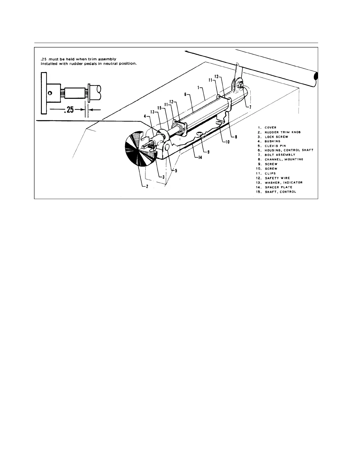
Figure 5-14. Rudder Trim Control
b. Before attaching the assembly to the mounting channel, ascertain that the clips (11) are installed so the
safety wire (12) will be on top. Also, that the threaded bushing (43 is installed on the assembly shaft
(15) with the welded attachment bushing forward or toward the housing.
c. Attach the housing lug to the arm provided on the rudder pedal torque tube and secure with bolt,
washer and nut (7). Tighten the nut only finger tight and safety with cotter pin.
d. Clamp the rudder pedals in neutral and position the threaded bushing in the mounting channel (8).
Turn the control shaft until the holes in the bushing and channel align and then install the clevis pin
and cotter pin (5). Should two thru holes be located in the aft end of the mounting channel, the pin
must be installed through the hole that will give equal travel and hit rudder stops before bottoming out
of the trim assembly.
e. With the rudder pedals neutral and no pressure fore or aft on the clevis pin, install the assembly cover
(1) so that the indicator washer (13) and the neutral mark on the cover align.
f. Install the trim cover, secure with screws, and install the trim control knob.
5-33. RIGGING AND ADJUSTMENT OF RUDDER TRIM CONTROLS. Perform these procedures only
after all other rudder and nose wheel rigging is complete. No adjustments are necessary other than those
required during installation of the assembly in the airplane as given in Paragraph 5-32.
5-34. WING FLAP CONTROLS.
5-35. REMOVAL OF WING FLAP CONTROLS. (Refer to Figure 5-15.)
a. The flap torque tube assembly may be removed by the following procedure:
1. Remove the access plate located between the underside of the aft section of each wing and the
fuselage by removing attaching screws.
2. Remove the two front seats and the rear seat floor panel.
Issued: 12/15/76
1G11
* CHEROKEE ARROW III SERVICE MANUAL
SURFACE CONTROLS