d. Fill the fuel tank with fuel. During filling check for proper fuel quantity gauge readings. Check for any
leaks around the sender unit attachment surface by looking through the access opening on the lower
surface of the wing.
e. Upon completion of the leak check, install the lower access panel and secure with required attachment
screws.
9-11. FUEL QUANTITY TRANSMITTER/GAUGE CHECK. Fuel quantity transmitter units and gauges may
be checked, while installed in the airplane, by the following procedure:
NOTE
To externally check the float assembly, see Figure 9-3 and Table IX-II.
When using the following procedure, the electrical system should apply 14-
volts to the gauge.
a. Turn the fuel selector valve off.
b. Completely drain the fuel tank that relates to the gauge to be checked.
c. Level the airplane longitudinally and laterally.
d. Turn the master switch on and observe the fuel quantity gauge. It should read empty. Refer to Table
IX-II for tolerances that are permitted between the fuel gauge reading and the actual fuel in the tank.
e. Add fuel to the tank in the amount of five U.S. gallon increments until the tank is full and observe
gauge readings.
NOTE
It is permissible to adjust the float assembly to obtain specified tolerances.
This adjustment should be accomplished per instructions titled Check and
Adjustment of Fuel Quantity Transmitters.
9-11a. FUEL QUANTITY INDICATOR.
The two fuel quantity gauges are mounted in the console on the instrument panel. These instruments are
calibrated in fractional divisions of one fourth, one half, three fourths and full. Two transmitter units are
installed in each fuel cell. These units contain a resistance strip and a movable control arm. The position of this
arm is controlled by a float in the fuel cell and this position is transmitted electrically to the indicator gauge to
show the amount of the fuel in the cell.
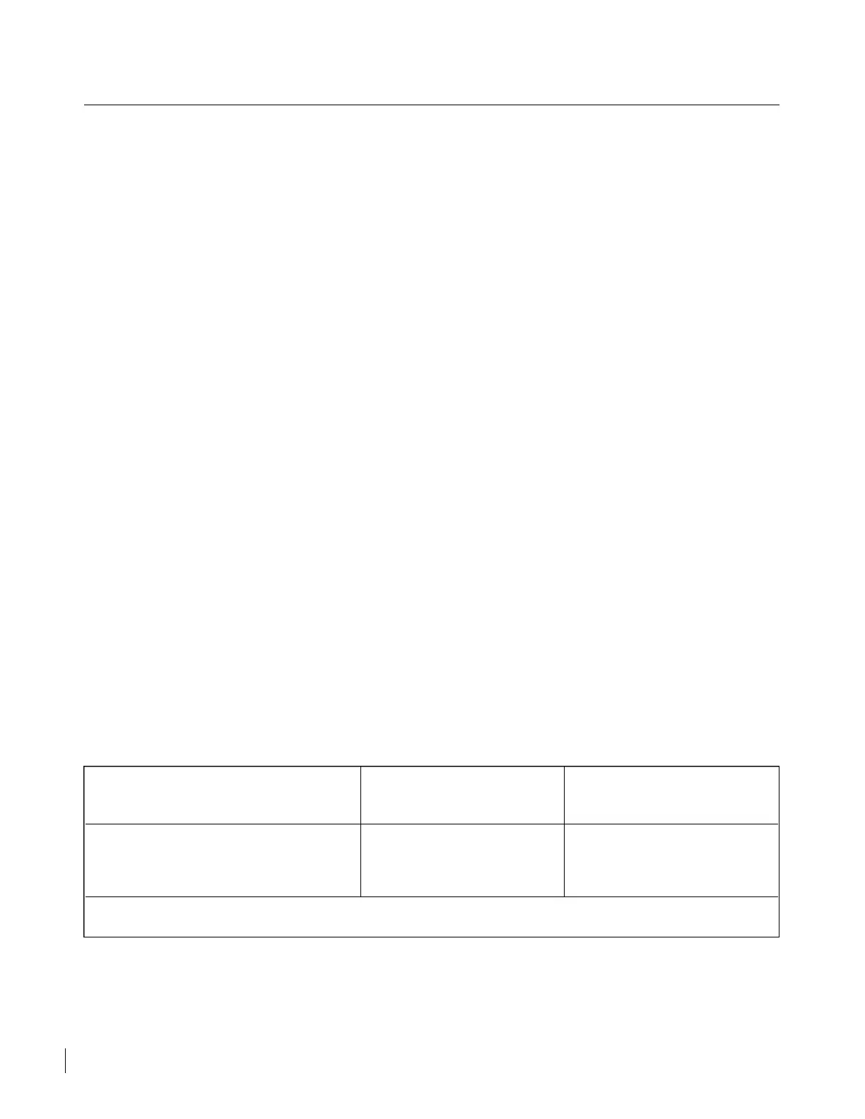
TABLE IX-II. FUEL QUANTITY TRANSMITTER CALIBRATION TOLERANCES
UNIT IDENTIFICATION FLOAT POSITION RESISTANCE
(See Note)
550 503 Piper 550 504 Empty 0 to 1.0 ohm max
0.9 in. above Empty 6.5 ± 0.5 ohms
7740-40 Rochester 7740-41 Full 45 ± 2 ohms
NOTE: Refer to Table IX-I for appropriate fuel sender location.
Revised: 2/13/89
2E18
CHEROKEE ARROW III SERVICE MANUAL
FUEL SYSTEM

 Loading...


