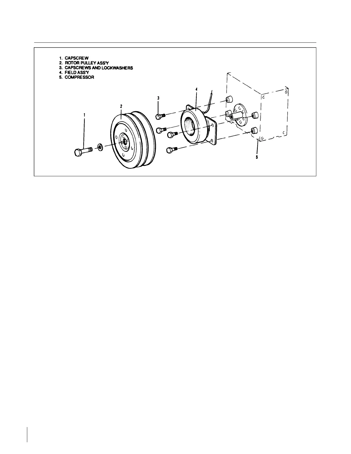
Figure 14-10. Magnetic Clutch (York Compressor)
14-24. MAGNETIC CLUTCH. (York Compressor)
14-25. MAGNETIC CLUTCH REMOVAL. (Refer to Figure 14-10.)
a. Remove the self-locking capscrew and washer (1) from the compressor shaft.
b. Insert a 5/8 -11 UNC-2B bolt in the threaded portion of the hub and tighten. The pressure exerted
by the bolt on the end of the compressor crankshaft will force off the rotor pulley assembly (2)
without damage to the clutch or compressor.
CAUTION
Do not use a wheel puller on the outer flange of the pulley. This can
damage the pulley grooves or clutch bearings.
c. Remove the four bolts securing the field assembly against the compressor bosses and remove the
bolts, washers and field assembly.
14-26. MAGNETIC CLUTCH INSTALLATION. (Refer to Figure 14-10.)
a. Position the field assembly (4) against the compressor bosses, with the electrical leads to the
cylinder side of the compressor.
b. Secure the field assembly (4) with four capscrews and lockwashers (3), do not torque at this time.
c. Connect the electrical lead from the field assembly.
NOTE
The compressor shaft must be clean and free from burrs.
Revised: 2/13/89
3B6
CHEROKEE ARROW III SERVICE MANUAL
ACCESSORIES AND UTILITIES