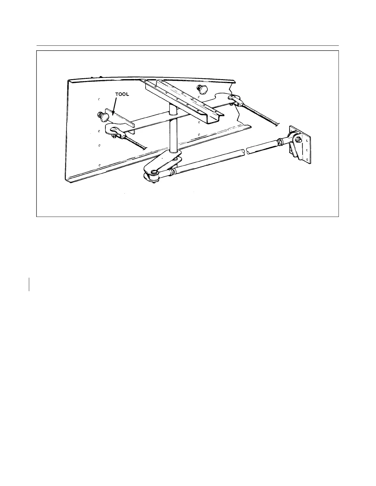
Figure 5-3. Bellcrank Rigging Tool
f. Remove the nut, pivot bolt (25) and washers that secure the bellcrank. The nut is visible from the
underside of the wing.
g. Remove the bellcrank from within the wing.
5-11. INSTALLATION OF AILERON BELLCRANK ASSEMBLY. (Refer to Figure 5-2.)
a. Ascertain that the bellcrank pivot bushing (26) and teflon tube (27) are installed in the torque tube
portion of the bellcrank (6).
b. Place the bellcrank in position in the wing with a washer located between each end of the torque tube
and the mounting location.
c. Install the bellcrank pivot bolt (25) with the head up. Install a washer and nut on the bolt, and torque
nut within 20 to 25 inch-pounds. Check that the bellcrank rotates freely with little up-down play.
d. Install and adjust control rod (7) and check aileron travel per Paragraph 5-12.
e. Connect the ends of the primary (13 or 17) and balance (18 or 19) control cables to the bellcrank using
bolts, washers, nuts and cotter pins. Allow the cable ends to rotate freely on the bellcrank.
f. Tighten the control cables at the balance cable turnbuckle (24) in the floor opening aft of the main
spar. Check cable tension per Paragraph 5-12.
g. Install the access plate on the underside of the wing and replace the floor panel.
Revised: 8/31/77
1F18
* CHEROKEE ARROW III SERVICE MANUAL
SURFACE CONTROLS