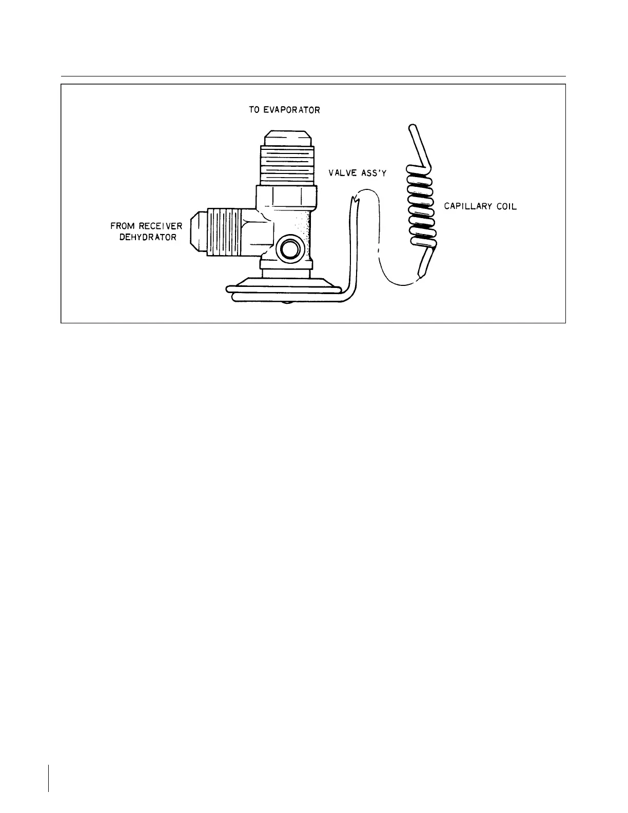
Figure 14-12. Expansion Valve
b. Adjust the push rods (9) so that a vertically measured gap of .16 of an inch exists along the trailing
edge of the door at the instant the forward edge of the door becomes flush with the fuselage skin.
c. With the door fully closed, adjust the CLOSED (6) limit switch so that the actuator (1) travels an
additional .12 of an inch after the door is fully closed, this is necessary to preload the mechanism.
Refer to Figure 14-11.
d. Cycle the assembly several times to be certain it operates properly without binding.
14-36. EXPANSION VALVE. (See Figure 14-12.)
14-37. EXPANSION VALVE REMOVAL. The expansion valve is located in the evaporator assembly between
the receiver drier and the evaporator inlet. The capillary coil is attached to the evaporator outlet line.
a. Remove the necessary access panels and discharge system.
b. Remove the capillary coil from the outlet line. (Do not link the capillary tube.)
c. Uncouple all related tube fittings. (See paragraph 14-5, B-7.)
NOTE
If this part is not serviceable, it must be replaced with a new part.
14-38. EXPANSION VALVE INSTALLATION.
a. Install the expansion valve in the inlet line of the evaporator core by coupling the related fittings.
(Seal all couplings with sealant applied to tube flanges only.) Torque fittings per Table XIV-I.
b. Secure the capillary coil to the evaporator outlet line.
c. Evacuate and charge the system. (See paragraphs 14-13 and 14-14.) Check for leaks. (See
paragraph 14-9.)
d. Replace access panels.
Revised: 2/13/89
3B10
CHEROKEE ARROW III SERVICE MANUAL
ACCESSORIES AND UTILITIES