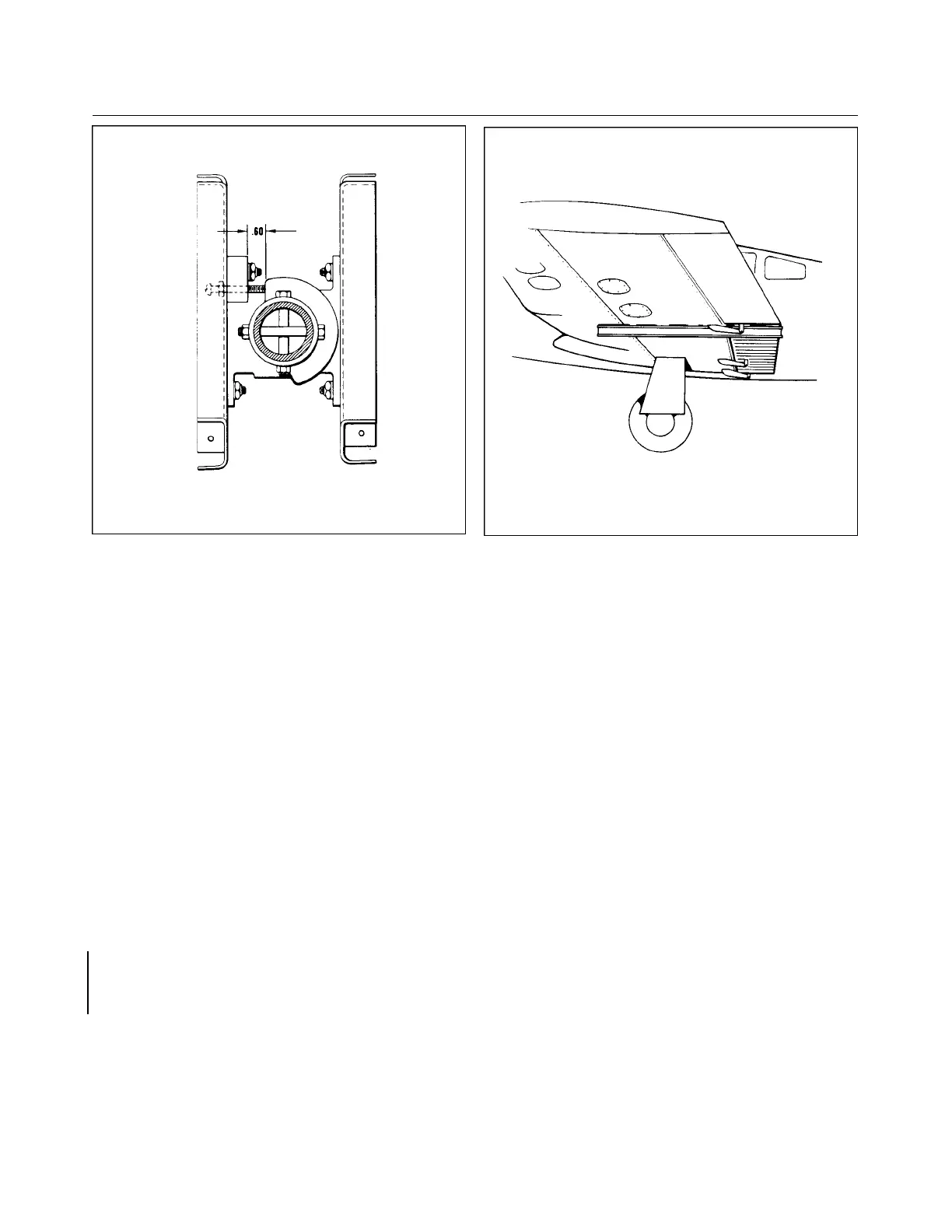
Figure 5-16. Flap Step Adjustment Figure 5-17. Flap Rigging Tool
7. Push the torque tube cranks (arms) (11) on each end of the torque tube and slide the stop fitting
(13) in place. Align the bolt hole of the crank and stop fitting with the holes in the torque tube and
install bolts. The holes in the stop fitting are longated to allow the stop fitting to be pushed against
the bearing blocks (7) thus allowing no side play of the assembly. Tighten the bolt assemblies (10)
on the stop fittings.
8. Install the tube support blocks (16 and 31) on their support brackets (19) and secure with bolts
(15).
9. Connect the flap return spring (32) to the return chain (30) and/or at the spar housing.
10. Connect the control cable end to the tension chain (20) and secure with bushing, clevis bolt, nut
and cotter pin.
11. Pull the flap handle full back and connect the tension spring (22). Release the flap handle to the
forward position.
12. Connect the flap control tube (4) to the flap and/or torque tube crank (11) and secure. The bolt (12)
and bushing that connects the control tube to the crank is installed through a hole in the side of the
fuselage located over the torque tube.
b. To install the flap handle (29) with bracket (28), place the assembly on the floor tunnel and secure with
bolts.
c. The flap control cable (23) may be installed by the following procedure:
1. Attach the cable and turnbuckle (25) to the flap handle arm and secure with clevis bolt, bushing*,
washer, nut and cotter pin (26). Ascertain that the turnbuckle end is free to rotate on the arm.
*(See latest revision of Piper Service Bulletin 965.)
2. Route the cable through the tunnel and spar housing.
3. Install the cable rub blocks on the aft side of the spar housing and secure with screws.
4. Install cotter pin cable guard over pulley (24) located just ahead of the spar housing in the floor
tunnel.
Interim Revision: 2/21/95
1G14
CHEROKEE ARROW III SERVICE MANUAL
SURFACE CONTROLS