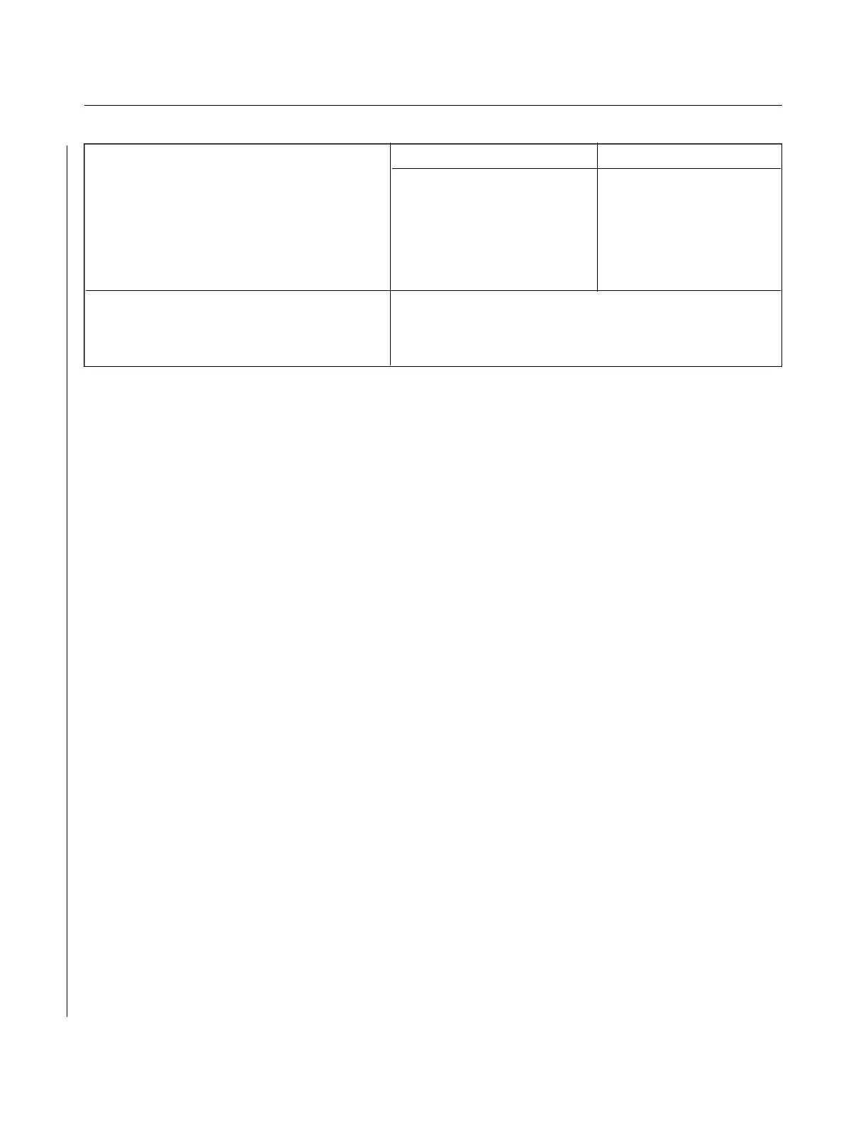
TABLE VI-I. LEADING PARTICULARS, HYDRAULIC SYSTEM
Hydraulic PRESTOLITE OILDYNE
High Pressure 2250 +/-250 psi 2400 +/-200 psi
Low Pressure 650 +/-150 psi 600 +/-200 psi
Flow Rate @ 1000 psi 45 cu. in. per min. 60cu.in.per min.
High Pressure Control 1600 to 2000 psi 2400 +/-200 psi
Thermal Relief 2250 +/-250 psi 3000 + 300-200 psi
Hydraulic Fluid MIL-H-5606A MIL-H-5606
Pressure Switch
Open (OFF) Pressure 1800 +/-100 psi
Close (ON) Pressure 300 +/-psi below opening pressure
6-4. HYDRAULIC PUMP. (PRESTOLITE, OILDYNE)
6-5. REMOVAL OF HYDRAULIC PUMP. The hydraulic pump with reservoir incorporated is located in the
aft section of the fuselage. Access to the pump is through the access panel in the aft wall of the baggage
compartment.
a. Disconnect the pump electrical leads from the pump solenoid relays and the ground wire from the
battery shelf.
b. Disconnect the hydraulic lines from the pump. Cap the line ends to prevent contamination.
c. Remove the pump by removing the pump attaching bolts.
WARNING
When servicing or inspecting vendor equipment installed in Piper aircraft, it
is the user’s responsibility to refer to the applicable vendor publication.
6-6. DISASSEMBLY OF HYDRAULIC PUMP. (PRESTOLITE) (Refer to Figure 6-3.) After the hydraulic
pump has been removed from the airplane, cap or plug all ports and clean the exterior of the pump with a dry
type solvent to remove accumulated dust or dirt. To disassemble any one of the three main components of the
pump, proceed as follows:
a. The base (16) of the pump may be removed from the case (15) as follows:
1. Cut the safety wire and remove the bolts (17) with washers that secure the base to the pump case.
2. The shuttle valve within the base should be removed for cleaning purposes only. To remove the
valve, cut safety wire. Remove plug with spring and valve.
NOTE
The shuttle valve and pump base are matched, lapped parts. Should it be
necessary to replace, replace as an assembly only.
b. Pump Motor: The pump motor may be removed from the pump and disassembled as follows:
1. Remove thru bolts (4) from head (1) of motor. Using a knife, cut the seal coating between the
motor head and case.
2. Lift the head up from the case approximately .50 of an inch, this will allow inspection of brushes
(3) without the brushes unseating from the commutator. (Refer to Paragraph 6-7, b for brush
inspection.) The brush heads are secured to the head assembly.
3. Raise the head assembly (1) off the armature (8) and note the small thrust ball (7) located between
the end of the armature (8) and motor head. Do not misplace this bearing.
Revised: 2/13/89
1H12
* CHEROKEE ARROW III SERVICE MANUAL
HYDRAULIC SYSTEM